Tomographic reconstruction
Tomographic reconstruction is a type of multidimensional inverse problem where the challenge is to yield an estimate of a specific system from a finite number of projections.The mathematical basis for tomographic imaging was laid down by Johann Radon. A notable example of applications is in Computed Tomography where cross-sectional images of patients are obtained in non-invasive manner. Recent developments have seen the Radon transform and its inverse used for tasks related to realistic object insertion required for testing and evaluating Computed Tomography use in Airport Security.[1]
This article applies in general to tomographic reconstruction for all kinds of tomography, but some of the terms and physical descriptions refer directly to X-ray computed tomography.
Description

The projection of an object, resulting from the tomographic measurement process at a given angle , is made up of a set of line integrals (see Fig. 1). A set of many such projections under different angles organized in 2D is called sinogram (see Fig. 3). In X-ray CT, the line integral represents the total attenuation of the beam of x-rays as it travels in a straight line through the object. As mentioned above, the resulting image is a 2D (or 3D) model of the attenuation coefficient. That is, we wish to find the image . The simplest and easiest way to visualise the method of scanning is the system of parallel projection, as used in the first scanners. For this discussion we consider the data to be collected as a series of parallel rays, at position , across a projection at angle . This is repeated for various angles. Attenuation occurs exponentially in tissue:


where is the attenuation coefficient as a function of position. Therefore generally the total attenuation of a ray at position, on the projection at angle , is given by the line integral:


Using the coordinate system of Figure 1, the value of onto which the point will be projected at angle is given by:


So the equation above can be rewritten as

where represents . This function is known as the Radon transform (or sinogram) of the 2D object.

The Fourier Transform of a projection can be written as
where [2]
![{\displaystyle P_{\theta }(\omega )=\int _{-\infty }^{\infty }\int _{-\infty }^{\infty }f(x,y)\exp[-j\omega (x\cos \theta +y\sin \theta )]\,dx\,dy=F(\Omega _{1},\Omega _{2})}](../I/m/36306c36f50bf7f3e670ee9136027e64f08b056a.svg)

Thus, projection of a system is represented as a slice of a 2D Fourier transform of the system in the frequency domain. Using the inverse Fourier transform, the inverse Randon transform formula can be easily derived.

where is the derivative of the Hilbert transform of the


In theory, inverse Radon transformation would yield the original image. The projection-slice theorem tells us that if we had an infinite number of one-dimensional projections of an object taken at an infinite number of angles, we could perfectly reconstruct the original object, . However, there will only be a finite number of projections available in practice.
Assuming has effective diameter and desired resolution is , rule of thumb number of projections needed for reconstruction is [2]


Reconstruction algorithms[2]
Fourier-Domain Reconstruction Algorithm[3]
Reconstruction can be made using interpolation. Assume -projections of are generated at equally spaced angles, each sampled at same rate. Discrete Fourier transform on each projection will yield sampling in frequency domain. Combining all the frequency-sampled projections would generate polar raster in frequency domain. Polar raster will be sparse so interpolation is used to fill the unknown DFT points and reconstruction can be done through inverse Discrete Fourier transform. Reconstruction performance may improve by designing methods to change the sparsity of polar raster, facilitating the effectiveness of interpolation.

For instance, concentric square raster in frequency domain can be obtained by changing the angle between each projection with equation

where is highest frequency to be evaluated.

Concentric square raster improves computational efficiency by allowing all the interpolation positions to be on rectangular DFT lattice. Furthermore, it reduces the interpolation error.[3]
Back Projection Algorithm[2]
In practice of tomographic image reconstruction, often a stabilized and discretized version of the inverse Radon transform is used, known as the filtered back projection algorithm.
With sampled discrete system, inverse Radon Transform is


where is the angular spacing between the projections and is radon kernel with frequency response .


The name back-projection comes from the fact that 1D projection needs to be filtered by 1D Radon kernel (back-projected) in order to obtain 2D signal. The filter used does not contain DC gain, thus adding DC bias may be desirable. Reconstruction using back-projection allows better resolution than interpolation method described above. However, it induces greater noise because the filter is prone to amplify high-frequency content.
Iterative Reconstruction Algorithm[2]
Iterative algorithm is computationally intensive but it allows to include a priori information about the system .
Let be the number of projections, be the distortion operator for th projection taken at an angle . are set of parameters to optimize the conversion of iterations.


![{\displaystyle f_{k}(x,y)=f_{k-1}(x,y)+\sum _{i=1}^{N}\lambda _{i}[p_{\theta _{i}}(r)-D_{i}f_{k-1}(x,y)]}](../I/m/d03e2569148c3e447738b0e62c161e4852051eb6.svg)
An alternative family of recursive tomographic reconstruction algorithms are the Algebraic Reconstruction Technique.
Fan-Beam Reconstruction
Use of noncollimated fan beam is common since collimated beam of radiation is difficult to obtain. Fan beams will generate series of line integrals, not parallel to each other, as projections. The fan-beam system will require 360 degres range of angles which impose mechanical constraint however, it allows faster signal acquisition time which may be advantageous in certain settings such as in the field of medicine. Back projection follows similar 2 step procedure that yield reconstruction by computing weighted sum back-projections obtained from filtered projections.
Tomographic reconstruction software
For flexible tomographic reconstruction, open source toolboxes are available, such as TomoPy [4] or the ASTRA toolbox .[5][6] TomoPy is an open-source Python toolbox to perform tomographic data processing and image reconstruction tasks at the Advanced Photon Source at Argonne National Laboratory. TomoPy toolbox is specifically designed to be easy to use and deploy at a synchrotron facility beamline. It supports reading many common synchrotron data formats from disk through Scientific Data Exchange,[7] and includes several other processing algorithms commonly used for synchrotron data. TomoPy also includes several reconstruction algorithms, which can be run on multi-core workstations and large-scale computing facilities.[8] The ASTRA Toolbox is a MATLAB toolbox of high-performance GPU primitives for 2D and 3D tomography, from 2009-2014 developed by iMinds-Vision Lab, University of Antwerp and since 2014 jointly developed by iMinds-VisionLab, UAntwerpen and CWI, Amsterdam. The toolbox supports parallel, fan, and cone beam, with highly flexible source/detector positioning. A large number of reconstruction algorithms are available through TomoPy and the ASTRA toolkit, including FBP, Gridrec, ART, SIRT, SART, BART, CGLS, PML, MLEM and OSEM. Recently, the ASTRA toolbox has been integrated in the TomoPy framework.[9] By integrating the ASTRA toolbox in the TomoPy framework, the optimized GPU-based reconstruction methods become easily available for synchrotron beamline users, and users of the ASTRA toolbox can more easily read data and use TomoPy’s other functionality for data filtering and artifact correction.
Gallery
Shown in the gallery is the complete process for a simple object tomography and the following tomographic reconstruction based on ART.
-

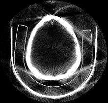
Fig. 2: Phantom object, two kitty-corner squares.
-
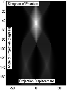
Fig. 3: Sinogram of the phantom object (Fig.2) resulting from tomography. 50 projection slices were taken over 180 degree angle, equidistantly sampled (only by coincidence the x-axis marks displacement at -50/50 units).
-

Fig.4: ART based tomographic reconstruction of the sinogram of Fig.3, presented as animation over the iterative reconstruction process. The original object could be approximatively reconstructed, as the resulting image has some visual artifacts.
References
- ↑ Megherbi, N., Breckon, T.P., Flitton, G.T., Mouton, A. (October 2013). "Radon Transform based Metal Artefacts Generation in 3D Threat Image Projection". Proc. SPIE Optics and Photonics for Counterterrorism, Crime Fighting and Defence (PDF). 8901. SPIE. pp. 1–7. doi:10.1117/12.2028506. Retrieved 5 November 2013.
- 1 2 3 4 5 Dudgeon and Mersereau (1984). Multidimensional digital signal processing. Prentice-Hall.
- 1 2 R. Mersereau, A. Oppenheim (1974). "Digital reconstruction of multidimensional signals from their projections". Proceedings of the IEEE. 62: 1319–1338.
- ↑ Gursoy D, De Carlo F, Xiao X, and Jacobsen C (2014). "TomoPy: A framework for the analysis of synchrotron tomographic data". Journal of Synchrotron Radiation. 22: 1188–1193. doi:10.1107/S1600577514013939.
- ↑ Van Aarle, W., Palenstijn, W.J., De Beenhouwer, J., Altantzis T., Bals S., Batenburg K. J., and J. Sijbers (October 2015). "The ASTRA Toolbox: a platform for advanced algorithm development in electron tomography". Ultramicroscopy. 157: 35–47. doi:10.1016/j.ultramic.2015.05.002.
- ↑ W. Van Aarle, W J. Palenstijn, J. Cant, E. Janssens, F. Bleichrodt, A. Dabravolski, J. De Beenhouwer, K. J. Batenburg, and J. Sijbers (2016). "Fast and flexible X-ray tomography using the ASTRA toolbox". Optics Express. 24 (22): 35–47. doi:10.1364/OE.24.025129.
- ↑ De Carlo F, Gursoy D, Marone F, Rivers M, Parkinson YD, Khan F, Schwarz N, Vine DJ, Vogt S, Gleber SC, Narayanan S, Newville M, Lanzirotti T, Sun Y, Hong YP, Jacobsen C (2014). "Scientific Data Exchange: a schema for HDF5-based storage of raw and analyzed data". Journal of Synchrotron Radiation. 22: 35–47. doi:10.1107/S160057751401604X.
- ↑ Bicer T, Gursoy D, Kettimuthu R, De Carlo F, and Foster I (2016). "Optimization of tomographic reconstruction workflows on geographically distributed resources". journal of Synchrotron Radiation. 23 (4): 997–1005. doi:10.1107/S1600577516007980.
- ↑ Pelt DM, Gursoy D, Batenburg KJ, De Carlo F, Palenstijna WJ, and Sijbers J (2016). "Integration of TomoPy and the ASTRA toolbox for advanced processing and reconstruction of tomographic synchrotron data". Journal of Synchrotron Radiation. 23: 842–849. doi:10.1107/S1600577516005658.
Further reading
- Avinash Kak & Malcolm Slaney (1988), Principles of Computerized Tomographic Imaging, IEEE Press, ISBN 0-87942-198-3.
- Bruyant, P.P. "Analytic and iterative reconstruction algorithms in SPECT" Journal Of Nuclear Medicine 43(10):1343-1358, 2002
External links
- http://www.slaney.org/pct/
- http://www.itk.org/ Insight ToolKit; open source tomographic support software
- http://tomopy.readthedocs.org
- http://visielab.uantwerpen.be/research/tomography ASTRA (All Scales Tomographic Reconstruction Antwerp) toolbox; very flexible, fast and open source software for computed tomographic reconstruction
- http://niftyrec.scienceontheweb.net/ NiftyRec; comprehensive open source tomographic reconstruction software; Matlab and Python scriptable
- http://tomviz.org/ Open-source tomographic reconstruction and visualization tool.