Three-dimensional losses and correlation in turbomachinery
Three-dimensionality in turbomachine increases complexity in flow field so, determination of losses becomes difficult unlike two-dimensional losses where equation complexity is little. Three-dimensionality includes large pressure gradients in every direction, design/curvature of blade, shock wave, heat transfer, cavitation and viscous effects, which generates secondary flow, vortices, tip leakage vortices and other losses. Viscous effects in turbomachinery causes blockage to the flow by formation of viscous layers around blade profile which effect pressure rise/fall and reduce effective area of flow field. Interaction between these losses in rotor increase instability and decreases in efficiency of turbomachinery. In calculation of three-dimensional losses every parameter comes into picture of flow path like axial spacing between vane and blade rows, end wall curvature, radial distribution of pressure gradient, hup/tip ratio, dihedral, lean, tip clearance, flare, aspect ratio, skew, sweep, platform cooling holes, surface roughness, off take bleeds. Associated with blade profile like camber distribution, stagger angle, blade spacing, blade camber, chord, surface roughness, leading and trailing edge radii, maximum thickness. So, correlations are dependent on so many parameter it becomes difficult to correlate. Correlation based on geometric similarity has been developed by many industries in form of charts, graphs, data statistics and performance data. Two-dimensional losses are easily evaluated by Navier-Stokes code but three-dimensional losses are difficult to evaluate so, correlation is used. Three-dimensional losses are mainly classified as:
- Three-dimensional profile losses
- Three-dimensional shock losses
- Secondary flow
- Endwall losses in axial turbomachinery
- Tip leakage flow losses
Three-dimensional profile losses
Main points are-

- Profile Losses occurs due to curvature of blade. It includes span-wise mixing of flow field in addition to two-dimensional mixing losses (can be predicted from Navier-Stokes code).
- In rotors major losses occur by radial pressure gradient from midspan to tip (flow ascending to tip).
- Reduction in high loses between Annulus wall and tip clearance region which includes trailing edge of blade profile. This is due to flow mixing and flow redistribution at the inner radius as flow proceeds downstream.
- Between hub and annulus wall, losses are prominent due to three-dimensionality.
- In single stage turbomachinery, shows large radial pressure gradient loss at exit of rotor.
- Platform cooling increases the endwall flow loss and coolant air increases profile loss.
- Navier-Stokes identifies much of the losses when some assumption are made like unseparated flow, etc. Here correlation is no longer justified.
Three-dimensional shock losses
Main points are-

- Shock losses continuously increases from hub to tip of blade in both supersonic and transonic rotor.
- Shock losses are accompanied by shock-boundary layer interaction losses, boundary layer losses in profile secondary flow and tip clearance effects.
- From Mach number prospective, fluid inside rotor is in supersonic phase except at initial hub entry.
- Mach number increases gradually from midspan to tip. At tip effect get dominated because of secondary flow, tip clearance effect and annulus wall boundary layer.
- In fan, shock losses increases overall efficiency by 2% because absence of tip clearance effect and secondary flow is present.
- As stated earlier correlation depends on many parameters, it is difficult to correlate.
- Correlation based on geometric similarity is used.

Secondary flow
Main points are-
- A rotation of blade row causes non-uniformity in radial velocity, stagnation pressure, stagnation enthalpy and stagnation temperature.It get distributed in both tangential direction and radial direction causes to generate secondary flow.
- Secondary flow generates two velocity components Vy, Vz, Hence introduce three-dimensionality in the flow field.
- The two component of velocity results in flow turning at tailing end of blade profile, which directly effect pressure drop and rise in turbomachinery. Hence efficiency decreases.
- Secondary flow generates vibration, noise and flutter because of unsteady pressure field between blades and rotor-stator interaction.
- Secondary flow introduces vortex cavitation which blocks flow rate, decrease performance and damage blade profile.
- Temperature flow field and cooling in turbomachinery also gets effected.
- Correlation for secondary flow given by Dunham(1970)
ζs = (0.0055 + 0.078(δ1/C)1/2)CL2 (cos3α2/cos3αm) (C/h) (C/S)2 ( 1/cos ά1)
ζs= average secondary flow loss coefficient, flow angles (α2, αm),inlet boundary layer everything(δ1/C) and blade geometry (C,S,h).
Endwall losses in Axial flow in turbomachinery
Main Points are-
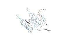
- In turbine, Secondary flow forces wall boundary layer toward suction side of rotor where mixing of blade and wall boundary takes place resulting in endwall losses.
- Now Secondary flow carries core losses away from wall and blade boundary layer through formation of vortices. So, peak loss occurs away for endwall.
- Endwall losses are high in stator (Francis turbine/Kaplan turbine) and nozzle vane (Pelton turbine) and loss distribution is different for turbine and compressor due to flow is opposite to each other.
- Due to presence of vortices, large flow-turning and secondary flow result to form a complex flow field and interaction of these effects increases endwall losses.
- In total loss, Endwall losses forms fraction of secondary losses given by Gregory-Smith et al. 1998. Hence secondary flow theory for small flow turning fails.
- Correlation for endwall losses in axial flow turbine is given by
                  ζ = ζp + ζew
     ζ = ζp[ 1 + ( 1 + ( 4ε / ( ρ2V2/ρ1V1 )1/2 ) ) ( S cos α2 - tTE )/h ]
ζ=total losses, ζp=blade profile losses, ζew= endwall losses.
- Expression for endwall losses in axial flow compressor is given by
η = ή ( 1 - ( δh* + δt*)/h ) / ( 1 - ( Fθh + Fθt ) / h )
η=efficiency in absence of endwall boundary layer and h is refer to hub while t is refer to tip. Value of Fθ and δ* derived from graph/chart.
Tip Leakage Flow Losses
Main points are-
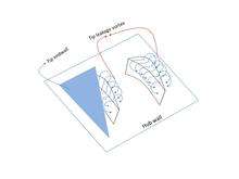
- Rotation of rotor in turbomachinery induce pressure difference across opposite side of the blade profile resulting in tip leakage.
- In turbomachinery rotor a gap between annulus wall and blade causes leakage and it also occur in gap between rotating hub and stator.
- Direct loss through clearance volume, as no angular momentum is transfer to fluid. So, work done is nil.
- Leakage and its interaction with other losses in flow field is very complex and hence it has profound effect than secondary flow at the tip.
- Leakage flow induce three-dimensionality, like mixing of leakage flow with vortex formation, entrainment process, diffusion and convection.This result in aerodynamics losses and inefficiency.
- Tip leakage and clearance loss account for 20%-40% of total losses.
- Effects cooling requirements in turbines and causes vibration, noise, flutter, high blade stress.
- Leakage flow causes low static pressure in core area, raising risk of cavitation and blade damage.
- Leakage velocity is given as-
QL = 2 ( ( Pp - Ps ) / ρ )1/2
- Leakage flow sheet due to velocity induced by the vortex given by Rains 1954
a/τ = 0.14 ( d/τ ( CL )1/2 )0.85
- Total loss in clearance volume is given by two equations-
ζL ~ ( CL2 * C * τ * cos2β1 ) / ( A * S * S * cos2βm )
ζW ~ ( δS* + δP* / S ) * ( 1 / A ) * ( ( CL )3/2) * ( τ / S )3/2Vm3 / ( V2 * V12 )
Links
- Secondary flow
- Turbomachinery
- http://arc.aiaa.org/doi/abs/10.2514/2.5694?journalCode=jpp
- http://www.task.gda.pl/files/quart/TQ2006/02/TQ210R-E.PDF
- http://www.edforall.net/index.php/engineering-a-technology/aeronautical-engineering/80-fluid-mechanics-ii/1662-introduction-to-3d-wings
- http://scholar.google.co.in/scholar?q=Fluid+dynamics+and+Heat+Transfer&hl=en&as_sdt=0&as_vis=1&oi=scholart&sa=X&ei=hWunUdKXJIuzrAe4joH4Bg&ved=0CDcQgQMwAA
- http://scholar.google.co.in/scholar?q=three+dimensional+losses+and+correlation+in+turbomachinery&btnG=&hl=en&as_sdt=0%2C5&as_vis=1
- http://www.annualreviews.org/doi/abs/10.1146/annurev.fl.05.010173.001335
- http://arc.aiaa.org/doi/abs/10.2514/2.491?journalCode=aiaaj
- http://pic.sagepub.com/content/213/2/107.short
See also
- Effects of Mach number and shock losses in turbomachines
- Axial compressor
- Centrifugal
- Centrifugal compressor
- Centrifugal fan
- Centrifugal pump
- Francis turbine
- Kaplan turbine
- Mechanical fan
References
- Chapter 4,5,6 In Fluid dynamics and Heat Transfer by Budugur Lakshminarayana
- Fluid dynamics and Heat Transfer by James George Knudsen, Donald La Verne Katz
- Turbomachinery: Design and Theory (Marcell Dekker) by Rama S.R. Gorla
- Handbook of Turbomachinery, 2nd Edition (Mechanical Engineering, No. 158) by Earl Logan, Jr; Ramendra
- Turbines Compressors and Fans by S M Yahya
- Principles of Turbomachinery by R K Turton
- Turbomachinery Flow Physics and Dynamic Performance by Meinhard Schobeiril
- Torsional Vibration of Turbo-Machinery by Duncan Walker
- Turbomachinery Performance Analysis by R. I. Lewis
- Fluid Machinery: Performance, Analysis, and Design by Terry Wright
- Fluid Mechanics and Thermodynamics of Turbomachinery by S L Dixon
- Turbo-Machinery Dynamics by A. S. Rangwala