Tail rotor

The tail rotor is a smaller rotor mounted so that it rotates vertically or near-vertically at the end of the tail of a traditional single-rotor helicopter. The tail rotor's position and distance from the center of gravity allow it to develop thrust in the same direction as the main rotor's rotation, to counter the torque effect created by the main rotor. Tail rotors are simpler than main rotors since they require only collective changes in pitch to vary thrust. The pitch of the tail rotor blades is adjustable by the pilot via the anti-torque pedals, which also provide directional control by allowing the pilot to rotate the helicopter around its vertical axis.
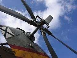
The tail rotor drive system consists of a shaft powered from the main transmission and a gearbox mounted at the end of the tail boom. The drive shaft may consist of one long shaft or a series of shorter shafts connected at both ends with flexible couplings, that allow the drive shaft to flex with the tail boom. The gearbox at the end of the tailboom provides an angled drive for the tail rotor and may also include gearing to adjust the output to the optimum rotational speed for the tail rotor, measured in rotations per minute (RPM). On larger helicopters with a tail pylon, intermediate gearboxes are used to transition the tail rotor drive shaft from along the tailboom to the top of the pylon. The tail rotor pylon may also serve as a vertical stabilizing airfoil, to alleviate the power requirement for the tail rotor in forward flight. The tail rotor pylon may also serve to provide limited antitorque within certain airspeed ranges, in the event that the tail rotor or the tail rotor flight controls fail. About 10% of the engine power goes to the tail rotor.[1]
Design
The tail rotor system rotates airfoils, small wings called blades, that vary in pitch in order to vary the amount of thrust they produce. The blades most often utilize a composite material construction, such as a core made of aluminum honeycomb or plasticized paper honeycomb, covered in a skin made of aluminum or carbon fiber composite. Tail rotor blades are made with both symmetrical and asymmetrical airfoil construction. The pitch change mechanism uses a cable control system or control tubes that run from the anti-torque pedals in the cockpit to a mechanism mounted on the tail rotor gearbox. In larger helicopters, the pitch change mechanism is augmented by a hydraulic power control servo. In the event of a hydraulic system failure, the mechanical system is still able to control the tail rotor pitch, though the control resistance felt by the pilot will be considerably greater.
The tail rotor is powered by the helicopter's main power plant, and rotates at a speed proportional to that of the main rotor. In both piston and turbine powered helicopters, the main rotor and the tail rotor are mechanically connected through a freewheeling clutch system, which allows the rotors to keep turning in the event of an engine failure by mechanically de-linking the engine from both the main and tail rotors. During autorotation, the momentum of the main rotor continues to power the tail rotor and allow directional control. To optimize its function for forward flight, the blades of a tail rotor have no twist to reduce the profile drag, because the tail rotor is mounted with its axis of rotation perpendicular to the direction of flight.
Reliability and safety

The tail rotor and the systems that provide power and control for it are considered critically important for safe flight. As with many parts on a helicopter, the tail rotor, its transmission, and many parts in the drive system are often life-limited, meaning they are arbitrarily replaced after a certain number of flight hours, regardless of condition. Between replacements, parts are subject to frequent inspections utilizing visual as well as chemical methods such as fluorescent penetrant inspection to detect weak parts before they fail completely.
Despite the emphasis on reducing failures, they do occasionally occur, most often due to hard landings and tailstrikes, or foreign object damage. Though the tail rotor is considered essential for safe flight, the loss of tail rotor function does not necessarily result in a fatal crash. In cases where the failure occurs due to contact with the ground, the aircraft is already at low altitude and the pilot may be able to reduce collective and land the helicopter before it spins completely out of control. Should the tail rotor fail randomly during cruise flight, forward momentum will often provide some directional stability, as many helicopters are equipped with a vertical stabilizer. The pilot would then be forced to autorotate and make an emergency landing with significant forward airspeed, which is known as a running landing or roll-on landing.
The tail rotor itself is a hazard to ground crews working near a running helicopter. For this reason, tail rotors are painted with stripes of alternating colors to increase their visibility to ground crews while the tail rotor is spinning.
Alternative technologies
There have been three major alternative designs which attempt to solve the shortcomings of the tail rotor system.
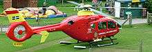
The first is to use a ducted fan rather than an un-ducted fan. This design is referred to as a fantail, or by the trade name Fenestron, a trademark of Eurocopter. Placing the fan within a duct reduces tip vortex losses, shields the tail rotor from damage, shields ground crews from the hazard of a spinning rotor, and is much quieter than a conventional tail rotor. The ducted fan uses shorter and more numerous blades, but otherwise it is very similar to a conventional tail rotor.
McDonnell Douglas developed the NOTAR (NO TAil Rotor) system, which eliminates having any rotating parts out in the open. The NOTAR system uses a variable pitch ducted fan driven by the helicopter's powerplant, but the ducted fan is mounted inside the fuselage ahead of the tail boom, and the exhaust passes through the tail boom to the end, where it is expelled out one side. This creates a boundary layer which causes the downwash from the main rotor to hug the tail boom according to the Coandă effect. This creates a force which cancels out the main rotor torque and provides directional control. The advantages of the system are similar to the Fenestron system discussed above.
There are at least four ways to eliminate the necessity of a tail rotor altogether :
- Tandem / Transverse rotors: to use two non-overlapping main rotors which turn in opposite directions, so that the torque created by one rotor cancels out the torque created by the other. Such a design is commonly seen on heavy lift helicopters like the tandem rotored CH-47 Chinook and effectively with the tiltrotor configuration V-22 Osprey.
- Coaxial. Other designs such as the Kamov Ka-50 and Sikorsky X2 use coaxial counter-rotating main rotors, which means that both rotors spin around the same axis but in opposite directions. The complexity of any dual main rotor system almost invariably requires the addition of a fly-by-wire flight control system, which increases costs drastically.
- Intermeshing rotors also turn in opposite directions, but rotate into each other without colliding. Invented by Anton Flettner and used in Flettner Fl 282,[2] Kaman HH-43 Huskie, and Kaman K-MAX.
- Tip jet. Another way to eliminate the effect of torque created by the rotorwing is by mounting the engine on the tips of the rotorwing rather than inside the helicopter itself; this is called a tip jet. One example of a helicopter using such a system is the NHI H-3 Kolibrie, which had a ramjet on each of the two wingtips, and an auxiliary power unit to spin up the rotor before starting the ramjets. Another example would be the Fairey Rotodyne. Also, unpowered rotors used in autogyro, gyrodyne, and derived concepts do not need a tail rotor either, although nearly all models that utilize this concept of propulsion do need a second prop in one way or another to drive them forward to begin with.
Recent technology in emergency tail rotor recovery systems has been advanced by the US Army in an SBIR research award to EATTS. The emergency anti-torque thruster system (EATTS) would allow a helicopter that has encountered tail rotor failure, or loss of tail rotor effectiveness, to land safely. The system is designed to counteract the torque from the helicopter's main rotor system during tail rotor failure as a result of mechanical problems as well as loss of the tail rotor from RPG hits.
See also
References
| Wikimedia Commons has media related to Helicopter tail rotors. |
- ↑ Dave Jackson. "Flight Dynamics - Definitions & Algorithms" UniCopter, 29 January 2013. Accessed: 19 November 2013.
- ↑ Boyne, Walter J. (2011). How the Helicopter Changed Modern Warfare. Pelican Publishing. p. 45. ISBN 1-58980-700-6.
- ↑ Rotorcraft Flying Handbook (PDF). U.S. Government Printing Office, Washington D.C.: U.S. Federal Aviation Administration. 2000. pp. 1–2 and 5–3. ISBN 1-56027-404-2. FAA-8083-21.