Symmetrical components
In electrical engineering, the method of symmetrical components simplifies analysis of unbalanced three-phase power systems under both normal and abnormal conditions. The basic idea is that an asymmetrical set of N phasors can be expressed as a linear combination of N symmetrical sets of phasors by means of a complex linear transformation.[1]
In the most common case of three-phase systems, the resulting "symmetrical" components are referred to as direct (or positive), inverse (or negative) and zero (or homopolar). The analysis of power system is much simpler in the domain of symmetrical components, because the resulting equations are mutually linearly independent if the circuit itself is balanced.
Description
In 1918 Charles Legeyt Fortescue presented a paper[2] which demonstrated that any set of N unbalanced phasors (that is, any such polyphase signal) could be expressed as the sum of N symmetrical sets of balanced phasors, for values of N that are prime. Only a single frequency component is represented by the phasors. However, the credit for the first formal statement should go to L.G. Stokvis[3] who explained the principal and gave experimental verification of its correctness in 1915. In a three-phase system, one set of phasors has the same phase sequence as the system under study (positive sequence; say ABC), the second set has the reverse phase sequence (negative sequence; ACB), and in the third set the phasors A, B and C are in phase with each other (zero sequence, the common-mode signal). Essentially, this method converts three unbalanced phases into three independent sources, which makes asymmetric fault analysis more tractable.
By expanding a one-line diagram to show the positive sequence, negative sequence and zero sequence impedances of generators, transformers and other devices including overhead lines and cables, analysis of such unbalanced conditions as a single line to ground short-circuit fault is greatly simplified. The technique can also be extended to higher order phase systems.
Physically, in a three phase winding a positive sequence set of currents produces a normal rotating field, a negative sequence set produces a field with the opposite rotation, and the zero sequence set produces a field that oscillates but does not rotate between phase windings. Since these effects can be detected physically with sequence filters, the mathematical tool became the basis for the design of protective relays, which used negative-sequence voltages and currents as a reliable indicator of fault conditions. Such relays may be used to trip circuit breakers or take other steps to protect electrical systems.
The analytical technique was adopted and advanced by engineers at General Electric and Westinghouse and after World War II it was an accepted method for asymmetric fault analysis.
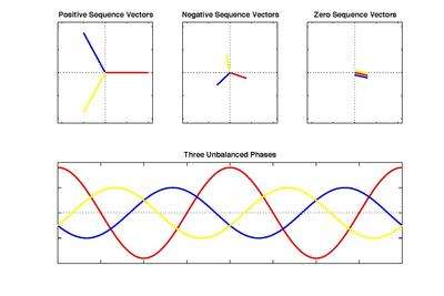
As shown in the figure to the above right, the three sets of symmetrical components (positive, negative, and zero sequence) add up to create the system of three unbalanced phases as pictured in the bottom of the diagram. The imbalance between phases arises because of the difference in magnitude and phase shift between the sets of vectors. Notice that the colors (red, blue, and yellow) of the separate sequence vectors correspond to three different phases (A, B, and C, for example). To arrive at the final plot, the sum of vectors of each phase is calculated. This resulting vector is the effective phasor representation of that particular phase. This process, repeated, produces the phasor for each of the three phases.
The three-phase case


Symmetrical components are most commonly used for analysis of three-phase electrical power systems. The voltage or current of a three-phase system at some point can be indicated by three phasors, called the three components of the voltage or the current.
This article discusses voltage, however, the same considerations also apply to current. In a perfectly balanced three-phase power system, the voltage phasor components have equal magnitudes but are 120 degrees apart. In an unbalanced system, the magnitudes and phases of the voltage phasor components are different.
Decomposing the voltage phasor components into a set of symmetrical components helps analyze the system as well as visualize any imbalances. If the three voltage components are expressed as phasors (which are complex numbers), a complex vector can be formed in which the three phase components are the components of the vector. A vector for three phase voltage components can be written as

and decomposing the vector into three symmetrical components gives

where the subscripts 0, 1, and 2 refer respectively to the zero, positive, and negative sequence components. The sequence components differ only by their phase angles, which are symmetrical and so are radians or 120°.

A matrix
Define a phasor rotation operator alpha, which rotates a phasor vector counterclockwise by 120 degrees:
- .

Note that α3 = 1 so that α−1 = α2.
The zero sequence components have equal magnitude and in phase with each other, therefore:
- ,

and the other phase sequences have the same magnitude, but their phases differ by 120°:

Thus,

where

Decomposition
The sequence components are derrived from the analysis equation

where

The above two equations tell how to derive symmetrical components corresponding to an asymmetrical set of three phasors:
- Sequence 0 is one-third the sum of the original three phasors.
- Sequence 1 is one-third the sum of the original three phasors rotated counterclockwise 0°, 120°, and 240°.
- Sequence 2 is one-third the sum of the original three phasors rotated counterclockwise 0°, 240°, and 120°.
Visually, if the original components are symmetrical, sequences 0 and 2 will each form a triangle, summing to zero, and sequence 1 components will sum to a straight line.
Intuition
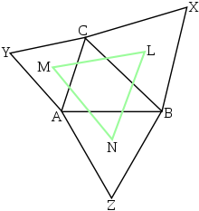
The phasors form a closed triangle (e.g., outer voltages or line to line voltages). To find the synchronous and inverse components of the phases, take any side of the outer triangle and draw the two possible equilateral triangles sharing the selected side as base. These two equilateral triangles represent a synchronous and an inverse system.

If the phasors V were a perfectly synchronous system, the vertex of the outer triangle not on the base line would be at the same position as the corresponding vertex of the equilateral triangle representing the synchronous system. Any amount of inverse component would mean a deviation from this position. The deviation is exactly 3 times the inverse phase component.
The synchronous component is in the same manner 3 times the deviation from the "inverse equilateral triangle". The directions of these components are correct for the relevant phase. It seems counter intuitive that this works for all three phases regardless of the side chosen but that is the beauty of this illustration.
The illustration is from Napoleon's Theorem.
Poly-phase case
It can be seen that the transformation matrix above is a discrete Fourier transform, and as such, symmetrical components can be calculated for any poly-phase system. However, by Pontryagin duality, only certain groups have a unique inverse, which is necessary for use in fault analysis.
Contribution of harmonics to symmetrical components in 3-phase power systems
Harmonics often occur in power systems as a consequence of non-linear loads. Each order of harmonics contributes to different sequence components. Harmonics of order make no contribution. Harmonics of order contribute to the zero sequence. Harmonics of order contribute to the negative sequence. Harmonics of order contribute to the positive sequence.


Consequence of the zero sequence component in power systems
The zero sequence represents the component of the unbalanced phasors that is equal in magnitude and phase. Because they are in phase, zero sequence currents flowing through an n-phase network will sum to n times the magnitude of the individual zero sequence currents components. Under normal operating conditions this sum is small enough to be negligible. However, during large zero sequence events such as lightning strikes, this nonzero sum of currents can lead to a larger current flowing through the neutral conductor than the individual phase conductors. Because neutral conductors are typically not larger than individual phase conductors, a large zero sequence component can lead to the overheating of neutral conductors and to fires. One way to prevent large zero sequence currents is to use a delta connection which appears as an open circuit to zero sequence currents.
See also
References
- Notes
- ↑ Hadjsaïd, Nouredine; Sabonnadière, Jean-Claude (2013). Power Systems and Restructuring. John Wiley & Sons. p. 244. ISBN 9781118599921.
- ↑ Charles L. Fortescue, "Method of Symmetrical Co-Ordinates Applied to the Solution of Polyphase Networks". Presented at the 34th annual convention of the AIEE (American Institute of Electrical Engineers) in Atlantic City, N.J. on 28 June 1918. Published in: AIEE Transactions, vol. 37, part II, pages 1027–1140 (1918). For a brief history of the early years of symmetrical component theory, see: J. Lewis Blackburn, Symmetrical Components for Power Engineering (Boca Raton, Florida: CRC Press, 1993), pages 3–4.
- ↑ Stokvis, L.G. (1914). "Sur la creation des harmoniques 3 dans les alternateurs par suite du desequilibrage des phases.". Comptes Rendus. vol.159: p.46.
- Bibliography
- J. Lewis Blackburn Symmetrical Components for Power Systems Engineering, Marcel Dekker, New York (1993). ISBN 0-8247-8767-6
- William D. Stevenson, Jr. Elements of Power System Analysis Third Edition, McGraw-Hill, New York (1975). ISBN 0-07-061285-4.
- History article from IEEE on early development of symmetrical components, retrieved May 12, 2005.
- Westinghouse Corporation, Applied Protective Relaying, 1976, Westinghouse Corporation, no ISBN, Library of Congress card no. 76-8060 - a standard reference on electromechanical protective relays