Subdivision surface
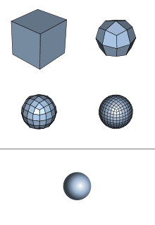
A subdivision surface, in the field of 3D computer graphics, is a method of representing a smooth surface via the specification of a coarser piecewise linear polygon mesh. The smooth surface can be calculated from the coarse mesh as the limit of recursive subdivision of each polygonal face into smaller faces that better approximate the smooth surface.
Overview
Subdivision surfaces are defined recursively. The process starts with a given polygonal mesh. A refinement scheme is then applied to this mesh. This process takes that mesh and subdivides it, creating new vertices and new faces. The positions of the new vertices in the mesh are computed based on the positions of nearby old vertices. In some refinement schemes, the positions of old vertices might also be altered (possibly based on the positions of new vertices).
This process produces a finer mesh than the original one, containing more polygonal faces. This resulting mesh can be passed through the same refinement scheme again and so on.
The limit subdivision surface is the surface produced from this process being iteratively applied infinitely many times. In practical use however, this algorithm is only applied a limited number of times. The limit surface can also be calculated directly for most subdivision surfaces using the technique of Jos Stam,[1] which eliminates the need for recursive refinement. Subdivision surfaces and T-Splines are competing technologies. Mathematically, subdivision surfaces are spline surfaces with singularities.[2]
Refinement schemes
Subdivision surface refinement schemes can be broadly classified into two categories: interpolating and approximating. Interpolating schemes are required to match the original position of vertices in the original mesh. Approximating schemes are not; they can and will adjust these positions as needed. In general, approximating schemes have greater smoothness, but editing applications that allow users to set exact surface constraints require an optimization step.
There is another division in subdivision surface schemes as well, the type of polygon that they operate on. Some function for quadrilaterals (quads), while others operate on triangles.
Approximating schemes
Approximating means that the limit surfaces approximate the initial meshes and that after subdivision, the newly generated control points are not in the limit surfaces. Examples of approximating subdivision schemes are:
- Catmull–Clark (1978) generalized bi-cubic uniform B-spline to produce their subdivision scheme. For arbitrary initial meshes, this scheme generates limit surfaces that are C2 continuous everywhere except at extraordinary vertices where they are C1 continuous (Peters and Reif 1998).
- Doo–Sabin - The second subdivision scheme was developed by Doo and Sabin (1978) who successfully extended Chaikin's corner-cutting method for curves to surfaces. They used the analytical expression of bi-quadratic uniform B-spline surface to generate their subdivision procedure to produce C1 limit surfaces with arbitrary topology for arbitrary initial meshes.
- Loop, Triangles - Loop (1987) proposed his subdivision scheme based on a quartic box spline of six direction vectors to provide a rule to generate C2 continuous limit surfaces everywhere except at extraordinary vertices where they are C1 continuous.
- Mid-Edge subdivision scheme - The mid-edge subdivision scheme was proposed independently by Peters–Reif (1997) and Habib–Warren (1999). The former used the midpoint of each edge to build the new mesh. The latter used a four-directional box spline to build the scheme. This scheme generates C1 continuous limit surfaces on initial meshes with arbitrary topology.
- √3 subdivision scheme - This scheme has been developed by Kobbelt (2000): it handles arbitrary triangular meshes, it is C2 continuous everywhere except at extraordinary vertices where it is C1 continuous and it offers a natural adaptive refinement when required. It exhibits at least two specificities: it is a Dual scheme for triangle meshes and it has a slower refinement rate than primal ones.
Interpolating schemes
After subdivision, the control points of the original mesh and the new generated control points are interpolated on the limit surface. The earliest work was the butterfly scheme by Dyn, Levin and Gregory (1990), who extended the four-point interpolatory subdivision scheme for curves to a subdivision scheme for surface. Zorin, Schröder and Sweldens (1996) noticed that the butterfly scheme cannot generate smooth surfaces for irregular triangle meshes and thus modified this scheme. Kobbelt (1996) further generalized the four-point interpolatory subdivision scheme for curves to the tensor product subdivision scheme for surfaces. Deng and Ma (2013) further generalized the four-point interpolatory subdivision scheme to arbitrary degree.
- Butterfly, Triangles - named after the scheme's shape
- Midedge, Quads
- Kobbelt, Quads - a variational subdivision method that tries to overcome uniform subdivision drawbacks
- Deng-Ma, Quads - 2n point subdivision generalized to arbitrary odd degree[3]
Editing a subdivision surface
Subdivision surfaces can be naturally edited at different levels of subdivision. Starting with basic shapes you can use binary operators to create the correct topology. Then edit the coarse mesh to create the basic shape, then edit the offsets for the next subdivision step, then repeat this at finer and finer levels. You can always see how your edits affect the limit surface via GPU evaluation of the surface.
A surface designer may also start with a scanned in object or one created from a NURBS surface. The same basic optimization algorithms are used to create a coarse base mesh with the correct topology and then add details at each level so that the object may be edited at different levels. These types of surfaces may be difficult to work with because the base mesh does not have control points in the locations that a human designer would place them. With a scanned object this surface is easier to work with than a raw triangle mesh, but a NURBS object probably had well laid out control points which behave less intuitively after the conversion than before.
See also
- T-vertices, a problem resulting from a finer mesh attaching to a coarser mesh.
- OpenSubdiv, an open source subdivision surface library released by Pixar
- CGAL, an open source geometry library that implements subdivision (see 3d Polyhedra)
- CGoGN, an open source geometry library that implements subdivision and hierarchical/multiresolution data structures
- Smoothing
- Level of detail
Key developments
- 1978: Subdivision surfaces were discovered simultaneously by Edwin Catmull and Jim Clark (see Catmull–Clark subdivision surface). In the same year, Daniel Doo and Malcom Sabin published a paper building on this work (see Doo–Sabin subdivision surface).
- 1995: Ulrich Reif characterized subdivision surfaces near extraordinary vertices[4] by treating them as splines with singularities.[2]
- 1998: Jos Stam contributed a method for exact evaluation for Catmull–Clark and Loop subdivision surfaces under arbitrary parameter values.[1]
References
- 1 2 Stam, J. (1998). "Exact evaluation of Catmull-Clark subdivision surfaces at arbitrary parameter values". Proceedings of the 25th annual conference on Computer graphics and interactive techniques - SIGGRAPH '98 (PDF). pp. 395–404. doi:10.1145/280814.280945. ISBN 0-89791-999-8. (downloadable eigenstructures)
- 1 2 Peters, J. R.; Reif, U. (2008). "Subdivision Surfaces". Geometry and Computing. 3. doi:10.1007/978-3-540-76406-9. ISBN 978-3-540-76405-2.
- ↑ http://dl.acm.org/citation.cfm?id=2487231
- ↑ Reif, U. (1995). "A unified approach to subdivision algorithms near extraordinary vertices". Computer Aided Geometric Design. 12 (2): 153–201. doi:10.1016/0167-8396(94)00007-F.
- Peters, J.; Reif, U. (October 1997). "The simplest subdivision scheme for smoothing polyhedra". ACM Transactions on Graphics. 16 (4): 420–431. doi:10.1145/263834.263851.
- Habib, A.; Warren, J. (May 1999). "Edge and vertex insertion for a class C1 of subdivision surfaces". Computer Aided Geometric Design. 16 (4): 223–247. doi:10.1016/S0167-8396(98)00045-4.
- Kobbelt, L. (2000). "√3-subdivision". Proceedings of the 27th annual conference on Computer graphics and interactive techniques - SIGGRAPH '00. pp. 103–112. doi:10.1145/344779.344835. ISBN 1-58113-208-5.
Further reading
- Joe D. Warren; Henrik Weimer (2002). Subdivision Methods for Geometric Design: A Constructive Approach. Morgan Kaufmann. ISBN 978-1-55860-446-9.
- Jörg Peters; Ulrich Reif (2008). Subdivision Surfaces. Springer Science & Business Media. ISBN 978-3-540-76405-2.
- Lars-Erik Andersson; Neil Frederick Stewart (2010). Introduction to the Mathematics of Subdivision Surfaces. SIAM. ISBN 978-0-89871-761-7.
External links
- Geri's Game : Oscar-winning animation by Pixar completed in 1997 that introduced subdivision surfaces (along with cloth simulation)
- Subdivision for Modeling and Animation tutorial, SIGGRAPH 1999 course notes
- Subdivision of Surface and Volumetric Meshes, software to perform subdivision using the most popular schemes
- Surface Subdivision Methods in CGAL, the Computational Geometry Algorithms Library
- Surface and Volumetric Subdivision Meshes, hierarchical/multiresolution data structures in CGoGN
- Modified Butterfly method implementation in C++
- Volume Enclosed by Subdivision Surfaces
- http://on-demand.gputechconf.com/gtc/2014/video/S4856-subdivision-surfaces-industry-standard.mp4