Staple remover
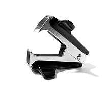
A staple remover is a device that allows for the quick removal of a staple from a material without causing damage. The best-known form of staple remover, designed for light-gauge staples, consists essentially of a) two opposing, pivot-mounted pairs of thin, steep wedges and b) a spring that returns the device to the open position after use. Although a simple metal wedge can be used for the same purpose, and although some staplers (especially small ones about 1.5 inches (3.8 cm) long) feature such a wedge at their hinge end, use of the wedge tends to tear fragile papers.
Use
Proper use of the opposing wedge staple remover is debated; the two major methods are described below.
Original ("fast") method
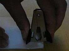
The user forcefully clips the front flat side of the staple, causing the folded tabs on the reverse side to open and pull through the entry holes. This method requires much less time. Although this method is quick, it can have the undesirable side effect of tearing the paper when the folded tabs pull through. Tearing usually does not occur when higher quality paper is used or the staple connects three or more sheets.
The inventor of the original staple remover, William G. Pankonin, illustrates this method of removal in US Patent Number 2033050.
"Safe" method
The following method reduces the risk of damage to the paper sheets being separated, albeit at some cost to speed and associated time efficiency:
- Turn the paper over to the side of the paper (usually the back) over which the staple's prongs have been folded.
- Use each opposed pair of tines to clip one of the prongs, re-straightening them and in the process raising them from the paper.
- Turn the paper back over to the front side against which the main body of the staple has been pressed.
- Gently slide the tines on one side of the remover under the main body of the staple and press the remover's halves together until you have a firm hold on the staple.
- Continuing to maintain a firm hold on the staple, pull the entire staple gently out of the paper.
Design

The design is focused on functionality and robustness with no unnecessary decoration (unless one includes the ergonomics of the handle) and minimised number of parts to lower costs and production time. The device works with a pincer action to unfold and pull out a staple in one motion. The modern staple remover is believed to have been conceptualised by an Irish housewife, Meghan Rooney. However, Miss Rooney had initially intended the design to function as an implement to remove stitching and not as a staple remover. Please note: The notch on a modern-day staple remover is to remove broken staples by hooking the aforementioned broken staple into the notch and utilising the standard pincer action.[1]
Components
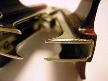
Blades
The two pivoting blades interlock each other. They are made of chrome-plated steel, which is harder than the thin ductile wire of the staple and strong enough to withstand the force required to remove it. The chrome plating provides a mild rust-resistance suitable for use in an office environment away from any liquids. Though the blade is made from what was originally sheet metal, the right angles and clean edges mean that a punch and die method of production would not be suitable. Therefore, the piece of sheet metal is cut using the process of blanking in a mechanical press, then bent in a press brake. This is a highly automated method which allows for a production rate of up to 1,500 units per minute.
Torsion springs
The torsion spring in this staple remover is a standardised component that appears in many other products, such as clothes pegs. It has two loops. The spring is made of chrome-plated steel, which is used because there is a point of minimum stress where continued use (opening and closing the staple remover) will not cause failure through fatigue. They are mass-produced by a spring winding machine which cold winds wire around an arbour before heat treating to make it harder. The spring is then chrome plated. The machinery to do this is large, expensive, but has a high production rate. That is why the springs are usually bought off-the-shelf from a tier 1 supplier rather than produced in house.
Plastic grips
The plastic grips are in fact unnecessary and the device could still be operated without them. They provide enhanced ergonomics so the user does not have to press their fingers against sheet metal. Injection moulding of thermoplastics are normally used through the use of an automated injection moulding machine, which shoots liquid plastic into a mould where it is left to set. Such processing is commonplace, not very labour-intensive, cheap, and capable of producing high quantities. Plastic is used as it is the easiest, but also the cheapest and most readily available material that can be formed into such fluid shapes.
Pin axle
The pin axle provides a cylindrical bar from which the blades can rotate. It is made of stainless steel, which will not rust in areas that have been worn by contact with other metals. The process to create such a pin axle is quite intensive and hence it is bought off-the-shelf from a supplier. They are made by a specialised machine which cuts thick wire into a suitable length and then die punches the head of the pin. The supplier normally runs specialised machinery that is capable of producing large amounts of products at a high rate for a low cost.
History
The form of destapler described above was invented by William G. Pankonin of Chicago, Illinois. A patent application for the same was filed on 12 December 1932, granted on 3 March 1936 and published on 3 April 1936 as patent document US 2,033,050.
A modified version, also capable of removing broken staples, was patented by Joseph A. Foitle of Overland Park, Kansas, but does not see widespread use, despite overcoming several disadvantages of the former device by a simple, yet novel and inventive, modification. The patent for the latter invention was filed on 28 May 1969 and was granted on 28 December 1971, published as US 3,630,486 A. An excerpt from the patent application reads as follows:
"... A device for removing broken portions of wire staples ... comprising a pair of overlying planar arms pivoted together on an axis normal thereto, said arms having cooperating notches ... whereby relative pivotal motions ... may be engaged over the projecting portion of a broken staple..."
See also
References
External links
![]() Media related to Staple removers at Wikimedia Commons
Media related to Staple removers at Wikimedia Commons