Shadow mapping

Shadow mapping or projective shadowing is a process by which shadows are added to 3D computer graphics. This concept was introduced by Lance Williams in 1978, in a paper entitled "Casting curved shadows on curved surfaces." Since then, it has been used both in pre-rendered and realtime scenes in many console and PC games.
Shadows are created by testing whether a pixel is visible from the light source, by comparing the pixel to a z-buffer or depth image of the light source's view, stored in the form of a texture.
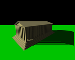
Principle of a shadow and a shadow map
If you looked out from a source of light, all of the objects you can see would appear in light. Anything behind those objects, however, would be in shadow. This is the basic principle used to create a shadow map. The light's view is rendered, storing the depth of every surface it sees (the shadow map). Next, the regular scene is rendered comparing the depth of every point drawn (as if it were being seen by the light, rather than the eye) to this depth map.
This technique is less accurate than shadow volumes, but the shadow map can be a faster alternative depending on how much fill time is required for either technique in a particular application and therefore may be more suitable to real time applications. In addition, shadow maps do not require the use of an additional stencil buffer, and can be modified to produce shadows with a soft edge. Unlike shadow volumes, however, the accuracy of a shadow map is limited by its resolution.
Algorithm overview
Rendering a shadowed scene involves two major drawing steps. The first produces the shadow map itself, and the second applies it to the scene. Depending on the implementation (and number of lights), this may require two or more drawing passes.
Creating the shadow map


The first step renders the scene from the light's point of view. For a point light source, the view should be a perspective projection as wide as its desired angle of effect (it will be a sort of square spotlight). For directional light (e.g., that from the Sun), an orthographic projection should be used.
From this rendering, the depth buffer is extracted and saved. Because only the depth information is relevant, it is common to avoid updating the color buffers and disable all lighting and texture calculations for this rendering, in order to save drawing time. This depth map is often stored as a texture in graphics memory.
This depth map must be updated any time there are changes to either the light or the objects in the scene, but can be reused in other situations, such as those where only the viewing camera moves. (If there are multiple lights, a separate depth map must be used for each light.)
In many implementations it is practical to render only a subset of the objects in the scene to the shadow map in order to save some of the time it takes to redraw the map. Also, a depth offset which shifts the objects away from the light may be applied to the shadow map rendering in an attempt to resolve stitching problems where the depth map value is close to the depth of a surface being drawn (i.e., the shadow casting surface) in the next step. Alternatively, culling front faces and only rendering the back of objects to the shadow map is sometimes used for a similar result.
Shading the scene
The second step is to draw the scene from the usual camera viewpoint, applying the shadow map. This process has three major components, the first is to find the coordinates of the object as seen from the light, the second is the test which compares that coordinate against the depth map, and finally, once accomplished, the object must be drawn either in shadow or in light.
Light space coordinates

In order to test a point against the depth map, its position in the scene coordinates must be transformed into the equivalent position as seen by the light. This is accomplished by a matrix multiplication. The location of the object on the screen is determined by the usual coordinate transformation, but a second set of coordinates must be generated to locate the object in light space.
The matrix used to transform the world coordinates into the light's viewing coordinates is the same as the one used to render the shadow map in the first step (under OpenGL this is the product of the modelview and projection matrices). This will produce a set of homogeneous coordinates that need a perspective division (see 3D projection) to become normalized device coordinates, in which each component (x, y, or z) falls between −1 and 1 (if it is visible from the light view). Many implementations (such as OpenGL and Direct3D) require an additional scale and bias matrix multiplication to map those −1 to 1 values to 0 to 1, which are more usual coordinates for depth map (texture map) lookup. This scaling can be done before the perspective division, and is easily folded into the previous transformation calculation by multiplying that matrix with the following:

If done with a shader, or other graphics hardware extension, this transformation is usually applied at the vertex level, and the generated value is interpolated between other vertices, and passed to the fragment level.
Depth map test

Once the light-space coordinates are found, the x and y values usually correspond to a location in the depth map texture, and the z value corresponds to its associated depth, which can now be tested against the depth map.
If the z value is greater than the value stored in the depth map at the appropriate (x,y) location, the object is considered to be behind an occluding object, and should be marked as a failure, to be drawn in shadow by the drawing process. Otherwise it should be drawn lit.
If the (x,y) location falls outside the depth map, the programmer must either decide that the surface should be lit or shadowed by default (usually lit).
In a shader implementation, this test would be done at the fragment level. Also, care needs to be taken when selecting the type of texture map storage to be used by the hardware: if interpolation cannot be done, the shadow will appear to have a sharp jagged edge (an effect that can be reduced with greater shadow map resolution).
It is possible to modify the depth map test to produce shadows with a soft edge by using a range of values (based on the proximity to the edge of the shadow) rather than simply pass or fail.
The shadow mapping technique can also be modified to draw a texture onto the lit regions, simulating the effect of a projector. The picture above, captioned "visualization of the depth map projected onto the scene" is an example of such a process.
Drawing the scene
Drawing the scene with shadows can be done in several different ways. If programmable shaders are available, the depth map test may be performed by a fragment shader which simply draws the object in shadow or lighted depending on the result, drawing the scene in a single pass (after an initial earlier pass to generate the shadow map).
If shaders are not available, performing the depth map test must usually be implemented by some hardware extension (such as GL_ARB_shadow), which usually do not allow a choice between two lighting models (lit and shadowed), and necessitate more rendering passes:
- Render the entire scene in shadow. For the most common lighting models (see Phong reflection model) this should technically be done using only the ambient component of the light, but this is usually adjusted to also include a dim diffuse light to prevent curved surfaces from appearing flat in shadow.
- Enable the depth map test, and render the scene lit. Areas where the depth map test fails will not be overwritten, and remain shadowed.
- An additional pass may be used for each additional light, using additive blending to combine their effect with the lights already drawn. (Each of these passes requires an additional previous pass to generate the associated shadow map.)
The example pictures in this article used the OpenGL extension GL_ARB_shadow_ambient to accomplish the shadow map process in two passes.
Shadow map real-time implementations
One of the key disadvantages of real time shadow mapping is that the size and depth of the shadow map determines the quality of the final shadows. This is usually visible as aliasing or shadow continuity glitches. A simple way to overcome this limitation is to increase the shadow map size, but due to memory, computational or hardware constraints, it is not always possible. Commonly used techniques for real-time shadow mapping have been developed to circumvent this limitation. These include Cascaded Shadow Maps,[1] Trapezoidal Shadow Maps,[2] Light Space Perspective Shadow maps,[3] or Parallel-Split Shadow maps.[4]
Also notable is that generated shadows, even if aliasing free, have hard edges, which is not always desirable. In order to emulate real world soft shadows, several solutions have been developed, either by doing several lookups on the shadow map, generating geometry meant to emulate the soft edge or creating non standard depth shadow maps. Notable examples of these are Percentage Closer Filtering,[5] Smoothies,[6] and Variance Shadow maps.[7]
Shadow mapping techniques
Simple
- SSM "Simple"
Splitting
- PSSM "Parallel Split" http://http.developer.nvidia.com/GPUGems3/gpugems3_ch10.html
- CSM "Cascaded" http://developer.download.nvidia.com/SDK/10.5/opengl/src/cascaded_shadow_maps/doc/cascaded_shadow_maps.pdf
Warping
- LiSPSM "Light Space Perspective" http://www.cg.tuwien.ac.at/~scherzer/files/papers/LispSM_survey.pdf
- TSM "Trapezoid" http://www.comp.nus.edu.sg/~tants/tsm.html
- PSM "Perspective" http://www-sop.inria.fr/reves/Marc.Stamminger/psm/
- CSSM "Camera Space" http://bib.irb.hr/datoteka/570987.12_CSSM.pdf
Smoothing
- PCF "Percentage Closer Filtering" http://http.developer.nvidia.com/GPUGems/gpugems_ch11.html
Filtering
- ESM "Exponential" http://www.cad.zju.edu.cn/home/jqfeng/papers/Exponential%20Soft%20Shadow%20Mapping.pdf
- CSM "Convolution" https://doclib.uhasselt.be/dspace/bitstream/1942/8040/1/3227.pdf
- VSM "Variance" http://citeseerx.ist.psu.edu/viewdoc/download?doi=10.1.1.104.2569&rep=rep1&type=pdf
- SAVSM "Summed Area Variance" http://http.developer.nvidia.com/GPUGems3/gpugems3_ch08.html
- SMSR "Shadow Map Silhouette Revectorization" http://bondarev.nl/?p=326
Soft Shadows
- PCSS "Percentage Closer" http://developer.download.nvidia.com/shaderlibrary/docs/shadow_PCSS.pdf
- SSSS "Screen space soft shadows" http://www.crcnetbase.com/doi/abs/10.1201/b10648-36
- FIV "Fullsphere Irradiance Vector" http://getlab.org/publications/FIV/
Assorted
- ASM "Adaptive" http://www.cs.cornell.edu/~kb/publications/ASM.pdf
- AVSM "Adaptive Volumetric" http://visual-computing.intel-research.net/art/publications/avsm/
- CSSM "Camera Space" http://free-zg.t-com.hr/cssm/
- DASM "Deep Adaptive"
- DPSM "Dual Paraboloid" http://sites.google.com/site/osmanbrian2/dpsm.pdf
- DSM "Deep" http://graphics.pixar.com/library/DeepShadows/paper.pdf
- FSM "Forward" http://www.cs.unc.edu/~zhangh/technotes/shadow/shadow.ps
- LPSM "Logarithmic" http://gamma.cs.unc.edu/LOGSM/
- MDSM "Multiple Depth" http://citeseerx.ist.psu.edu/viewdoc/download?doi=10.1.1.59.3376&rep=rep1&type=pdf
- RTW "Rectilinear" http://www.cspaul.com/wiki/doku.php?id=publications:rosen.2012.i3d
- RMSM "Resolution Matched" http://www.idav.ucdavis.edu/func/return_pdf?pub_id=919
- SDSM "Sample Distribution" http://visual-computing.intel-research.net/art/publications/sdsm/
- SPPSM "Separating Plane Perspective" http://image.diku.dk/projects/media/morten.mikkelsen.07.pdf
- SSSM "Shadow Silhouette" http://graphics.stanford.edu/papers/silmap/silmap.pdf
Miscellaneous
- Shadow Depth Maps (SDM)[8]
- Perspective shadow maps (PSMs)
- Light Space Perspective Shadow Maps (LSPSMs)
- Cascaded Shadow Maps (CSMs)[9]
- Variance Shadow Maps (VSMs)[10]
See also
- Shadow volume, another shadowing technique
- Ray casting, a slower technique often used in ray tracing
- Photon mapping, a much slower technique capable of very realistic lighting
- Radiosity, another very slow but very realistic technique
Further reading
- Smooth Penumbra Transitions with Shadow Maps Willem H. de Boer
- Forward shadow mapping performs the shadow test in eye-space rather than light-space to keep texture access more sequential.
References
- ↑ "Cascaded shadow maps" (PDF). NVidia. Retrieved 2008-02-14{{inconsistent citations}}
- ↑ Tobias Martin; Tiow-Seng Tan. "Anti-aliasing and Continuity with Trapezoidal Shadow Maps". Retrieved 2008-02-14.
- ↑ Michael Wimmer; Daniel Scherzer; Werner Purgathofer. "Light Space Perspective Shadow Maps". Retrieved 2008-02-14.
- ↑ Fan Zhang; Hanqiu Sun; Oskari Nyman. "Parallel-Split Shadow Maps on Programmable GPUs". Retrieved 2008-02-14.
- ↑ "Shadow Map Antialiasing". NVidia. Retrieved 2008-02-14.
- ↑ Eric Chan, Fredo Durand, Marco Corbetta. "Rendering Fake Soft Shadows with Smoothies". Retrieved 2008-02-14.
- ↑ William Donnelly; Andrew Lauritzen. "Variance Shadow Maps". Retrieved 2008-02-14.
- ↑ http://msdn.microsoft.com/en-us/library/windows/desktop/ee416324(v=vs.85).aspx
- ↑ http://msdn.microsoft.com/en-us/library/windows/desktop/ee416307(v=vs.85).aspx
- ↑ http://dl.acm.org/citation.cfm?doid=1111411.1111440
External links
- Hardware Shadow Mapping, nVidia
- Shadow Mapping with Today's OpenGL Hardware, nVidia
- Riemer's step-by-step tutorial implementing Shadow Mapping with HLSL and DirectX
- Improvements for Shadow Mapping using GLSL
- NVIDIA Real-time Shadow Algorithms and Techniques
- Shadow Mapping implementation using Java and OpenGL