Solar thermal collector
| Part of a series about |
| Sustainable energy |
|---|
 |
| Energy conservation |
| Renewable energy |
| Sustainable transport |
|
A solar thermal collector collects heat by absorbing sunlight. A collector is a device for capturing solar radiation. Solar radiation is energy in the form of electromagnetic radiation from the infrared (long) to the ultraviolet (short) wavelengths. The quantity of solar energy striking the Earth's surface (solar constant) averages about 1,000 watts per square meter under clear skies, depending upon weather conditions, location and orientation.
The term "solar collector" commonly refers to solar hot water panels, but may refer to installations such as solar parabolic troughs and solar towers; or basic installations such as solar air heaters. Concentrated solar power plants usually use the more complex collectors to generate electricity by heating a fluid to drive a turbine connected to an electrical generator.[1] Simple collectors are typically used in residential and commercial buildings for space heating. The first solar thermal collector designed for building roofs was patented by William H. Goettl and called the "Solar heat collector and radiator for building roof".[2]
Solar-thermal collectors heating liquid
Solar collectors are either non-concentrating or concentrating. In the non-concentrating type, the collector area (i.e., the area that intercepts the solar radiation) is the same as the absorber area (i.e., the area absorbing the radiation). In these types the whole solar panel absorbs light. Concentrating collectors have a bigger interceptor than absorber.[1]
Flat-plate and evacuated-tube solar collectors are used to collect heat for space heating, domestic hot water or cooling with an absorption chiller.
Flat plate collectors

Flat-plate collectors, developed by Hottel and Whillier in the 1950s, are the most common type. They consist of (1) a dark flat-plate absorber, (2) a transparent cover that reduces heat losses, (3) a heat-transport fluid (air, antifreeze or water) to remove heat from the absorber, and (4) a heat insulating backing. The absorber consists of a thin absorber sheet (of thermally stable polymers, aluminum, steel or copper, to which a matte black or selective coating is applied) often backed by a grid or coil of fluid tubing placed in an insulated casing with a glass or polycarbonate cover. In water heat panels, fluid is usually circulated through tubing to transfer heat from the absorber to an insulated water tank. This may be achieved directly or through a heat exchanger.
Most air heat fabricators and some water heat manufacturers have a completely flooded absorber consisting of two sheets of metal which the fluid passes between. Because the heat exchange area is greater they may be marginally more efficient than traditional absorbers.[3] Sunlight passes through the glazing and strikes the absorber plate, which heats up, changing solar energy into heat energy. The heat is transferred to liquid passing through pipes attached to the absorber plate. Absorber plates are commonly painted with "selective coatings", which absorb and retain heat better than ordinary black paint. Absorber plates are usually made of metal—typically copper or aluminum—because the metal is a good heat conductor. Copper is more expensive, but is a better conductor and less prone to corrosion than aluminum. (See: Copper in solar water heaters). In locations with average available solar energy, flat plate collectors are sized approximately one-half to one square foot per gallon of one day's hot water use. Absorber piping configurations include:
- harp – traditional design with bottom pipe risers and top collection pipe, used in low pressure thermosyphon and pumped systems;
- serpentine – one continuous S that maximizes temperature but not total energy yield in variable flow systems, used in compact solar domestic hot water only systems (no space heating role);
- flooded absorber consisting of two sheets of metal stamped to produce a circulation zone;
- boundary layer absorber collectors consisting of several layers of transparent and opaque sheets that enable absorption in a boundary layer. Because the energy is absorbed in the boundary layer, heat conversion may be more efficient than for collectors where absorbed heat is conducted through a material before the heat is accumulated in a circulating liquid.
Polymer flat plate collectors are an alternative to metal collectors and are now being produced in Europe. These may be wholly polymer, or they may include metal plates in front of freeze-tolerant water channels made of silicone rubber. Polymers are flexible and therefore freeze-tolerant and can employ plain water instead of antifreeze, so that they may be plumbed directly into existing water tanks instead of needing heat exchangers that lower efficiency. By dispensing with a heat exchanger, temperatures need not be quite so high for the circulation system to be switched on, so such direct circulation panels, whether polymer or otherwise, can be more efficient, particularly at low light levels. Some early selectively coated polymer collectors suffered from overheating when insulated, as stagnation temperatures can exceed the polymer's melting point.[4][5] For example, the melting point of polypropylene is 160 °C (320 °F), while the stagnation temperature of insulated thermal collectors can exceed 180 °C (356 °F) if control strategies are not used. For this reason polypropylene is not often used in glazed selectively coated solar collectors. Increasingly polymers such as high temperate silicones (which melt at over 250 °C (482 °F)) are being used. Some non polypropylene polymer based glazed solar collectors are matte black coated rather than selectively coated to reduce the stagnation temperature to 150 °C (302 °F) or less.
In areas where freezing is a possibility, freeze-tolerance (the capability to freeze repeatedly without cracking) can be achieved by the use of flexible polymers. Silicone rubber pipes have been used for this purpose in UK since 1999. Conventional metal collectors are vulnerable to damage from freezing, so if they are water filled they must be carefully plumbed so they completely drain using gravity before freezing is expected, so that they do not crack. Many metal collectors are installed as part of a sealed heat exchanger system. Rather than having potable water flow directly through the collectors, a mixture of water and antifreeze such as propylene glycol is used. A heat exchange fluid protects against freeze damage down to a locally determined risk temperature that depends on the proportion of propylene glycol in the mixture. The use of glycol lowers the water's heat carrying capacity marginally, while the addition of an extra heat exchanger may lower system performance at low light levels.
A pool or unglazed collector is a simple form of flat-plate collector without a transparent cover. Typically polypropylene or EPDM rubber or silicone rubber is used as an absorber. Used for pool heating it can work quite well when the desired output temperature is near the ambient temperature (that is, when it is warm outside). As the ambient temperature gets cooler, these collectors become less effective. Most flat plate collectors have a life expectancy of over 25 years.
Applications
The main use of this technology is in residential buildings where the demand for hot water has a large impact on energy bills. This generally means a situation with a large family, or a situation in which the hot water demand is excessive due to frequent laundry washing. Commercial applications include laundromats, car washes, military laundry facilities and eating establishments. The technology can also be used for space heating if the building is located off-grid or if utility power is subject to frequent outages. Solar water heating systems are most likely to be cost effective for facilities with water heating systems that are expensive to operate, or with operations such as laundries or kitchens that require large quantities of hot water. Unglazed liquid collectors are commonly used to heat water for swimming pools but can also be applied to large scale water pre-heating. When loads are large relative to available collector area the bulk of the water heating can be done at low temperature, lower than at swimming pool temperatures where unglazed collectors are well established in the marketplace as the right choice. Because these collectors need not withstand high temperatures, they can use less expensive materials such as plastic or rubber. Many unglazed collectors are made of polypropylene and must be drained fully to avoid freeze damage when air temperatures drop below 44F on clear nights.[6] A smaller but growing percentage of unglazed collectors are flexible meaning they can withstand water freezing solid inside their absorber. The freeze concern only need be the water filled piping and collector manifolds in a hard freeze condition. Unglazed solar hot water systems should be installed to "drainback" to a storage tank whenever solar radiation is insufficient. There are no thermal shock concerns with unglazed systems. Commonly used in swimming pool heating since solar energy's early beginnings, unglazed solar collectors heat swimming pool water directly without the need for antifreeze or heat exchangers. Hot water solar systems require heat exchangers due to contamination possibilities and in the case of unglazed collectors, the pressure difference between the solar working fluid (water) and the load (pressurized cold city water). Large scale unglazed solar hot water heaters like the one at the Minoru Aquatic Center in Richmond BC[7] operate at lower temperatures than evacuated tube or boxed and glazed collector systems so they require larger more expensive heat exchangers but all other components including vented storage tanks and uninsulated plastic PVC piping reduce costs of this alternative dramatically compared to the higher temperature collector types. When heating hot water we are actually heating cold to warm and warm to hot. We can heat cold to warm as efficiently with unglazed collectors as we can heat warm to hot with high temperature collectors
Evacuated tube collectors


Most vacuum tube collectors in use in middle Europe use heat pipes for their core instead of passing liquid directly through them. Direct flow is more popular in China. Evacuated heat pipe tubes (EHPTs) are composed of multiple evacuated glass tubes each containing an absorber plate fused to a heat pipe.[8] The heat is transferred to the transfer fluid (water or an antifreeze mix—typically propylene glycol) of a domestic hot water or hydronic space heating system in a heat exchanger called a "manifold". The manifold is wrapped in insulation and covered by a protective sheet metal or plastic case. The vacuum inside of the evacuated tube collectors have been proven to last more than 25 years, the reflective coating for the design is encapsulated in the vacuum inside of the tube, which will not degrade until the vacuum is lost.[9] The vacuum that surrounds the outside of the tube greatly reduces convection and conduction heat loss, therefore achieving greater efficiency than flat-plate collectors, especially in colder conditions. This advantage is largely lost in warmer climates, except in those cases where very hot water is desirable, e.g., for commercial processes. The high temperatures that can occur may require special design to prevent overheating.

Some evacuated tubes (glass-metal) are made with one layer of glass that fuses to the heat pipe at the upper end and encloses the heat pipe and absorber in the vacuum. Others (glass-glass) are made with a double layer of glass fused together at one or both ends with a vacuum between the layers (like a vacuum bottle or flask), with the absorber and heat pipe contained at normal atmospheric pressure. Glass-glass tubes have a highly reliable vacuum seal, but the two layers of glass reduce the light that reaches the absorber. Moisture may enter the non-evacuated area of the tube and cause absorber corrosion. Glass-metal tubes allow more light to reach the absorber, and protect the absorber and heat pipe from corrosion even if they are made from dissimilar materials (see galvanic corrosion).
The gaps between the tubes may allow for snow to fall through the collector, minimizing the loss of production in some snowy conditions, though the lack of radiated heat from the tubes can also prevent effective shedding of accumulated snow.[10][11]
Comparisons of flat plate and evacuated tube collectors
A longstanding argument exists between proponents of these two technologies. Some of this can be related to the physical structure of evacuated tube collectors which have a discontinuous absorbance area. An array of evacuated tubes on a roof has open space between the collector tubes, and vacuum between the two concentric glass tubes of each collector. Collector tubes cover only a fraction of a unit area of a roof. If evacuated tubes are compared with flat-plate collectors on the basis of area of roof occupied, a different conclusion might be reached than if the areas of absorber were compared. In addition, the ISO 9806 standard[12] is ambiguous in describing the way in which the efficiency of solar thermal collectors should be measured, since these could be measured either in terms of gross area or in terms of absorber area. Unfortunately, power output is not given for thermal collectors as it is for PV panels. This makes it difficult for purchasers and engineers to make informed decisions.
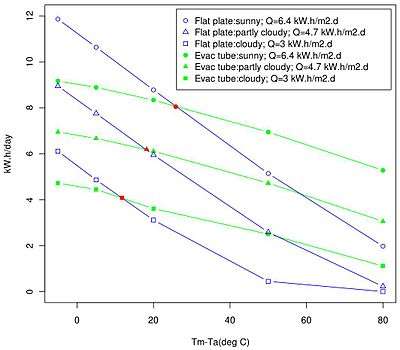 |
A comparison of the energy output (kW.h/day) of a flat plate collector (blue lines; Thermodynamics S42-P; absorber 2.8 m2) and an evacuated tube collector (green lines; SunMaxx 20EVT; absorber 3.1 m2. Data obtained from SRCC certification documents on the Internet. Tm-Ta = temperature difference between water in the collector and the ambient temperature. Q = insolation during the measurements. Firstly, as (Tm-Ta) increases the flat plate collector loses efficiency more rapidly than the evac tube collector. This means the flat plate collector is less efficient in producing water higher than 25 degrees C above ambient (i.e. to the right of the red marks on the graph). Secondly, even though the output of both collectors drop off strongly under cloudy conditions (low insolation), the evac tube collector yields significantly more energy under cloudiness than the flat plate collector. Although many factors obstruct the extrapolation from two collectors to two different technologies, above, the basic relationships between their efficiencies remain valid. |
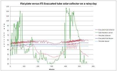 |
A field trial [13] illustrating the differences discussed in the figure on the left. A flat plate collector and a similar-sized evacuated tube collector were installed adjacently on a roof, each with a pump, controller and storage tank. Several variables were logged during a day with intermittent rain and cloud. Green line = solar irradiation. The top maroon line indicates the temperature of the evac tube collector for which cycling of the pump is much slower and even stopping for some 30 minutes during the cool parts of the day (irradiation low), indicating a slow rate of heat collection. The temperature of the flat plate collector fell significantly during the day (bottom purple line), but started cycling again later in the day when irradiation increased. The temperature in the water storage tank of the evac tube system (dark blue graph) increased by 8 degrees C during the day while that of the flat plate system (light blue graph) only remained constant. Courtesy ITS-solar.[13] |
Flat-plate collectors usually lose more heat to the environment than evacuated tubes, as an increasing function of temperature. They are inappropriate for high temperature applications such as process steam production. Evacuated tube collectors have a lower absorber plate area to gross area ratio (typically 60–80% of gross area) compared to flat plates. Based on absorber plate area, most evacuated tube systems are more efficient per square meter than equivalent flat plate systems. This makes them suitable where roof space is limiting, for example where the number of occupants of a building is higher than the number of square metres of suitable and available roof space. In general, per installed square metre, evacuated tubes deliver marginally more energy when the ambient temperature is low (e.g. during winter) or when the sky is overcast. However even in areas without much sunshine and solar heat, some low cost flat plate collectors can be more cost efficient than evacuated tube collectors. Although several European companies manufacture evacuated tube collectors, the evacuated tube market is dominated by manufacturers in the East. Several Chinese companies have track records of 15–30 years. There is no unambiguous evidence that the two designs differ in long term reliability. However, evacuated tube technology is younger and (especially for newer variants with sealed heat pipes) still need to demonstrate competitive lifetimes. The modularity of evacuated tubes can be advantageous in terms of extensibility and maintenance, for example if the vacuum in one tube diminishes.

For a given absorber area, evacuated tubes can therefore maintain their efficiency over a wide range of ambient temperatures and heating requirements. In most climates, flat-plate collectors will generally be more cost-effective than evacuated tubes. When employed in arrays and considered instead on a per square metre basis, the efficient but costly evacuated tube collectors can have a net benefit in winter and summer. They are well-suited to cold ambient temperatures and work well in situations of consistently low sunshine, providing heat more consistently than flat plate collectors per square metre. Heating of water by a medium to low amount (i.e. Tm-Ta) is much more efficiently performed by flat plate collectors. Domestic hot water frequently falls into this medium category. Glazed or unglazed flat collectors are the preferred devices for heating swimming pool water.[15] Unglazed collectors may be suitable in tropical or subtropical environments if domestic hot water needs to be heated by less than 20 °C. A contour map can show which type is more effective (both thermal efficiency and energy/cost) for any geographic region.
EHPT's work as a thermal one-way valve due to their heat pipes. This gives them an inherent maximum operating temperature that acts as a safety feature. They have less aerodynamic drag, which may allow them to be placed onto the roof without being tied down. They can collect thermal radiation from the bottom in addition to the top. Tubes can be replaced individually without stopping the entire system. There is no condensation or corrosion within the tubes. One hurdle to wider adoption of evacuated tube collectors in some markets is their inability to pass internal thermal shock tests where ISO 9806-2 section 9 class b is a requirement for durability certification.[16] This means that if unprotected evacuated tube collectors are exposed to full sun for too long prior to being filled with cold water the tubes may shatter due to the rapid temperature shift. There is also the question of vacuum leakage. Flat panels have been around much longer and are less expensive. They may be easier to clean. Other properties, such as appearance and ease of installation are more subjective.
Bowl
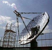
A solar bowl is a type of solar thermal collector that operates similarly to a parabolic dish, but instead of using a tracking parabolic mirror with a fixed receiver, it has a fixed spherical mirror with a tracking receiver. This reduces efficiency, but makes it cheaper to build and operate. Designers call it a fixed mirror distributed focus solar power system. The main reason for its development was to eliminate the cost of moving a large mirror to track the sun as with parabolic dish systems.[17]
A fixed parabolic mirror creates a variously shaped image of the sun as it moves across the sky. Only when the mirror is pointed directly at the sun does the light focus on one point. That is why parabolic dish systems track the sun. A fixed spherical mirror focuses the light in the same place independent of the sun's position. The light, however, is not directed to one point but is distributed on a line from the surface of the mirror to one half radius (along a line that runs through the sphere center and the sun).

As the sun moves across the sky, the aperture of any fixed collector changes. This causes changes in the amount of captured sunlight, producing what is called the sinus effect of power output. Proponents of the solar bowl design claim the reduction in overall power output compared with tracking parabolic mirrors is offset by lower system costs.[17]
The sunlight concentrated at the focal line of a spherical reflector is collected using a tracking receiver. This receiver is pivoted around the focal line and is usually counterbalanced. The receiver may consist of pipes carrying fluid for thermal transfer or photovoltaic cells for direct conversion of light to electricity.
The solar bowl design resulted from a project of the Electrical Engineering Department of the Texas Technical University, headed by Edwin O'Hair, to develop a 5 MWe power plant. A solar bowl was built for the town of Crosbyton, Texas as a pilot facility.[17] The bowl had a diameter of 65 ft (20 m), tilted at a 15° angle to optimize the cost/yield relation (33° would have maximized yield). The rim of the hemisphere was "trimmed" to 60°, creating a maximum aperture of 3,318 square feet (308.3 m2). This pilot bowl produced electricity at a rate of 10 kW peak.
A 15-meter diameter Auroville solar bowl was developed from an earlier test of a 3.5-meter bowl in 1979–1982 by the Tata Energy Research Institute. That test showed the use of the solar bowl in the production of steam for cooking. The full-scale project to build a solar bowl and kitchen ran from 1996, and was fully operational by 2001.
Solar-thermal collectors heating air
A simple solar air collector consists of an absorber material, sometimes having a selective surface, to capture radiation from the sun and transfers this thermal energy to air via conduction heat transfer. This heated air is then ducted to the building space or to the process area where the heated air is used for space heating or process heating needs. Functioning in a similar manner as a conventional forced air furnace, solar-thermal-air systems provide heat by circulating air over an energy collecting surface, absorbing the sun’s thermal energy, and ducting air coming in contact with it. Simple and effective collectors can be made for a variety of air conditioning and process applications.
A variety of applications can utilize solar air heat technologies to reduce the carbon footprint from use of conventional heat sources, such as fossil fuels, to create a sustainable means to produce thermal energy. Applications such as space heating, greenhouse season extension, pre-heating ventilation makeup air, or process heat can be addressed by solar air heat devices. In the field of ‘solar co-generation’ solar thermal technologies are paired with photovoltaics (PV) to increase the efficiency of the system by taking heat away from the PV collectors, cooling the PV panels to improve their electrical performance while simultaneously warming air for space heating.
Space heating and ventilating
Space heating for residential and commercial applications can be done through the use of solar air heating panels. This configuration operates by drawing air from the building envelope or from the outdoor environment and passing it through the collector where the air warms via conduction from the absorber and is then supplied to the living or working space by either passive means or with the assistance of a fan. A pioneering figure of this type of system was George Löf, who built solar heated air system for a house in Boulder, Colorado, in 1945. He later included a gravel bed for heat storage.
Ventilation, fresh air or makeup air is required in most commercial, industrial and institutional buildings to meet code requirements. By drawing air through a properly designed unglazed transpired air collector or an air heater the solar heated fresh air can reduce the heating load during daytime operation. Many applications are now being installed where the transpired collector preheats the fresh air entering a heat recovery ventilator to reduce the defrost time of HRV's. The higher your ventilation and temperature the better your payback time will be.
Process heating
Solar air heat is also used in process applications such as drying laundry, crops (i.e. tea, corn, coffee) and other drying applications. Air heated through a solar collector and then passed over a medium to be dried can provide an efficient means by which to reduce the moisture content of the material.
Solar air heating collector types
Collectors are commonly classified by their air-ducting methods as one of three types:
- through-pass collectors
- front-pass
- back pass
- combination front and back pass collectors
Collectors can also be classified by their outer surface:
- glazed
- unglazed
Through-pass air collector
Offering the highest efficiency of any solar technology the through-pass configuration, air ducted onto one side of the absorber passes through a perforated material and is heated from the conductive properties of the material and the convective properties of the moving air. Through-pass absorbers have the most surface area which enables relatively high conductive heat transfer rates, but significant pressure drop can require greater fan power, and deterioration of certain absorber material after many years of solar radiation exposure can additionally create problems with air quality and performance.
Back, front, and combination passage air collector
In back-pass, front-pass, and combination type configurations the air is directed on either the back, the front, or on both sides of the absorber to be heated from the return to the supply ducting headers. Although passing the air on both sides of the absorber will provide a greater surface area for conductive heat transfer, issues with dust (fouling) can arise from passing air on the front side of the absorber which reduces absorber efficiency by limiting the amount of sunlight received. In cold climates, air passing next to the glazing will additionally cause greater heat loss, resulting in lower overall performance of the collector.
Glazed systems
Glazed systems usually have a transparent top sheet and insulated side and back panels to minimize heat loss to ambient air. The absorber plates in modern panels can have absorptivity of more than 93%. Glazed Solar Collectors (recirculating types that are usually used for space heating). Air typically passes along the front or back of the absorber plate while scrubbing heat directly from it. Heated air can then be distributed directly for applications such as space heating and drying or may be stored for later use. Payback for glazed solar air heating panels can be less than 9–15 years depending on the fuel being replaced.
Unglazed systems
Unglazed systems, or transpired air systems have been used to heat make-up or ventilation air in commercial, industrial, agriculture and process applications. They consist of an absorber plate which air passes across or through as it scrubs heat from the absorber. Non-tranparent glazing materials are less expensive, and decrease expected payback periods. Transpired collectors are considered "unglazed" because their collector surfaces are exposed to the elements, are often not transparent and not hermetically sealed.
Unglazed transpired solar collectors
Background
The term "unglazed air collector" refers to a solar air heating system that consists of a metal absorber without any glass or glazing over top. The most common type of unglazed collector on the market is the transpired solar collector. The technology has been extensively monitored by these government agencies, and Natural Resources Canada developed the feasibility tool RETScreen™ to model the energy savings from transpired solar collectors. Since that time, several thousand transpired solar collector systems have been installed in a variety of commercial, industrial, institutional, agricultural, and process applications in countries around the world. The technology was originally used primarily in industrial applications such as manufacturing and assembly plants where there were high ventilation requirements, stratified ceiling heat, and often negative pressure in the building. With the increasing drive to install renewable energy systems on buildings, transpired solar collectors are now used across the entire building stock because of high energy production (up to 750 peak thermal Watts/square metre), high solar conversion (up to 90%) and lower capital costs when compared against solar photovoltaic and solar water heating.
Solar air heating is a renewable energy heating technology used to heat or condition air for buildings or process heat applications. It is typically the most cost-effective of all the solar technologies, especially in large scale applications, and it addresses the largest usage of building energy in heating climates, which is space heating and industrial process heating. They are either glazed or unglazed.
Method of operation
Unglazed air collectors heat ambient (outside) air instead of recirculated building air. Transpired solar collectors are usually wall-mounted to capture the lower sun angle in the winter heating months as well as sun reflection off the snow and achieve their optimum performance and return on investment when operating at flow rates of between 4 and 8 CFM per square foot (72 to 144 m3/h.m2) of collector area.
The exterior surface of a transpired solar collector consists of thousands of tiny micro-perforations that allow the boundary layer of heat to be captured and uniformly drawn into an air cavity behind the exterior panels. This heated ventilation air is drawn under negative pressure into the building’s ventilation system where it is then distributed via conventional means or using a solar ducting system.
Hot air that may enter an HVAC system connected to a transpired collector that has air outlets positioned along the top of the collector, particularly if the collector is west facing. To counter this problem, Matrix Energy has patented a transpired collector with a lower air outlet position and perforated cavity framing to perpetrate increased air turbulence behind the perforated absorber for increased performance.
This cutaway view shows the MatrixAir transpired solar collector components and air flow. The lower air inlet mitigates the intake of heated air to the HVAC system during summer operation.
The extensive monitoring by Natural Resources Canada and NREL has shown that transpired solar collector systems reduce between 10-50% of the conventional heating load and that RETScreen is an accurate predictor of system performance. Transpired solar collectors act as a rainscreen and they also capture heat loss escaping from the building envelope which is collected in the collector air cavity and drawn back into the ventilation system. There is no maintenance required with solar air heating systems and the expected lifespan is over 30 years.
Variations of transpired solar collectors
Unglazed transpired collectors can also be roof-mounted for applications in which there is not a suitable south facing wall or for other architectural considerations. Matrix Energy Inc. has patented a roof mounted product called the “Delta” a modular, roof-mounted solar air heating system where southerly, east or west facing facades are simply not available.
Each ten foot (3.05 m) module will deliver 250 CFM (425 m3/h)of preheated fresh air typically providing annual energy savings of 1100 kWh (4 GJ) annually. This unique two stage, modular roof mounted transpired collector operating a nearly 90% efficiency each module delivering over 118 l/s of preheated air per two square meter collector. Up to seven collectors may be connected in series in one row, with no limit to the number of rows connected in parallel along one central duct typically yielding 4 CFM of preheated air per square foot of available roof area. +
Transpired collectors can be configured to heat the air twice to increase the delivered air temperature making it suitable for space heating applications as well as ventilation air heating. In a 2-stage system, the first stage is the typical unglazed transpired collector and the second stage has glazing covering the transpired collector. The glazing allows all of that heated air from the first stage to be directed through a second set of transpired collectors for a second stage of solar heating.
Solar-thermal collectors generating electricity
Parabolic troughs, dishes and towers described in this section are used almost exclusively in solar power generating stations or for research purposes. Although simple, these solar concentrators are quite far from the theoretical maximum concentration.[18][19] For example, the parabolic trough concentration is about 1/3 of the theoretical maximum for the same acceptance angle, that is, for the same overall tolerances for the system. Approaching the theoretical maximum may be achieved by using more elaborate concentrators based on nonimaging optics.[18] Solar thermal collectors may also be used in conjunction with photovoltaic collectors to obtain combined heat and power.[20][21]
Parabolic trough

This type of collector is generally used in solar power plants. A trough-shaped parabolic reflector is used to concentrate sunlight on an insulated tube (Dewar tube) or heat pipe, placed at the focal point, containing coolant which transfers heat from the collectors to the boilers in the power station.
Parabolic dish

With a parabolic dish collector, one or more parabolic dishes concentrate solar energy at a single focal point, similar to the way a reflecting telescope focuses starlight, or a dish antenna focuses radio waves. This geometry may be used in solar furnaces and solar power plants.
The shape of a parabola means that incoming light rays which are parallel to the dish's axis will be reflected toward the focus, no matter where on the dish they arrive. Light from the sun arrives at the Earth's surface almost completely parallel. So the dish is aligned with its axis pointing at the sun, allowing almost all incoming radiation to be reflected towards the focal point of the dish. Most losses in such collectors are due to imperfections in the parabolic shape and imperfect reflection.
Losses due to atmospheric scattering are generally minimal. However, on a hazy or foggy day, light is diffused in all directions through the atmosphere, which reduces the efficiency of a parabolic dish significantly.
In dish stirling power plant designs, a stirling engine coupled to a dynamo, is placed at the focus of the dish. This absorbs the energy focused onto it and converts it into electricity.
Power tower
A power tower is a large tower surrounded by tracking mirrors called heliostats. These mirrors align themselves and focus sunlight on the receiver at the top of tower, collected heat is transferred to a power station below. This design reaches very high temperatures. High temperatures are suitable for electricity generation using conventional methods like steam turbine or a direct high temperature chemical reaction such as liquid salt.[22] By concentrating sunlight current systems can get better efficiency than simple solar cells. A larger area can be covered by using relatively inexpensive mirrors rather than using expensive solar cells. Concentrated light can be redirected to a suitable location via optical fiber cable for such uses as illuminating buildings. Heat storage for power production during cloudy and overnight conditions can be accomplished, often by underground tank storage of heated fluids. Molten salts have been used to good effect. Other working fluids, such as liquid metals, have also been proposed due to their superior thermal properties.[23]
However, concentrating systems require sun tracking to maintain sunlight focus at the collector. They are unable to provide significant power in diffused light conditions. Solar cells are able to provide some output even if the sky becomes cloudy, but power output from concentrating systems drops drastically in cloudy conditions as diffused light cannot be concentrated.
Standards
- ISO test methods for solar collectors.[24]
- EN 12975: Thermal solar systems and components. Solar collectors.
- EN 12976: Thermal solar systems and components. Factory made systems.
- EN 12977: Thermal solar systems and components. Custom made systems.
- Solar Keymark:[25] Thermal solar systems and components. Higher level EN 1297X series certification which includes factory visits.
See also
- Concentrated solar power
- Cross-linked polyethylene § PEX-AL-PEX
- Insulated glazing
- List of solar thermal power stations
- List of thermal conductivities
- Nanofluids in solar collectors
- Seasonal thermal energy storage (STES)
- Selective surface
- Solar cooker
- Solar Flower Tower
- Solar thermal energy
- Solar-assisted heat pump
- Trombe wall
- Zeolite
References
- 1 2 Norton, Brian (2013). Harnessing Solar Heat. Springer. ISBN 978-94-007-7275-5.
- ↑ https://www.google.com/patents/US4098260
- ↑ rise.org.au. "Domestic Hot Water Systems". Archived from the original on 9 March 2011. Retrieved 2008-10-29.
- ↑ "Polymeric absorbers for flat-plate collectors : Can venting provide adequate overheat protection?". Cat.inist.fr. Retrieved 2013-08-20.
- ↑ "Solar Thermal Collectors in Polymeric Materials: A Novel Approach Towards Higher Operating Temperatures - Springer". Springerlink.com. Retrieved 2013-08-20.
- ↑ Tom Lane, Solar Hot Water Systems, Lessons Learned 1977 to Today p7
- ↑ http://www.h2otsun.com/hotwater/minflyer.pdf
- ↑ "Vacuum Tube Liquid-Vapor (Heat-Pipe) Collectors" (PDF). Retrieved 2013-08-20.
- ↑ "Solar Evacuated Tube Collectors" (PDF). Retrieved 2013-10-06.
- ↑ "Solar Flat Plate vs. Evacuated Tube Collectors" (PDF). Retrieved 2013-08-20.
- ↑ Trinkl, Christoph; Wilfried Zörner; Claus Alt; Christian Stadler (2005-06-21). "Performance of Vacuum Tube and Flat Plate Collectors Concerning Domestic Hot Water Preparation and Room Heating" (PDF). 2nd European Solar Thermal Energy Conference 2005 (estec2005). CENTRE OF EXCELLENCE FOR SOLAR ENGINEERING at Ingolstadt University of Applied Sciences. Retrieved 2010-08-25.
- ↑ ISO 9806-2:1995. Test methods for solar collectors -- Part 2: Qualification test procedures. International Organization for Standardization, Geneva, Switzerland
- 1 2
- ↑ Tom Lane. Solar Hot Water Systems: Lessons Learned, 1977 to Today. p. 5.
- ↑ Flatplate vs. EHTP Archived December 3, 2010, at the Wayback Machine.
- ↑ FSEC test standard 102-10 section 5.6.
- 1 2 3 Calhoun, Fryor "Duel for the Sun" Texas Monthly November 1983
- 1 2 Chaves, Julio (2015). Introduction to Nonimaging Optics, Second Edition. CRC Press. ISBN 978-1482206739.
- ↑ Roland Winston et al., Nonimaging Optics, Academic Press, 2004 [ISBN 978-0127597515]
- ↑ Mojiri (2013). "Spectral beam splitting for efficient conversion of solar energy — A review". Renewable and Sustainable Energy Reviews. 28: 654–663. doi:10.1016/j.rser.2013.08.026.
- ↑ Taylor, R.A. (2012). "Nanofluid-based optical filter optimization for PV/T systems". Light: Science & Applications. 1: e34. doi:10.1038/lsa.2012.34.
- ↑ Woody, Todd. "Secret Ingredient To Making Solar Energy Work: Salt". Forbes magazine. Retrieved 13 March 2013.
- ↑ Boerema (2012). "Liquid sodium versus Hitec as a heat transfer fluid in solar thermal central receiver systems". Solar Energy. 86 (9): 2293–2305. doi:10.1016/j.solener.2012.05.001.
- ↑ "ISO 9806-1:1994 - Test methods for solar collectors -- Part 1: Thermal performance of glazed liquid heating collectors including pressure drop". iso.org. 2012. Retrieved September 17, 2012.
- ↑ "The Solar Keymark, The main quality label for solar thermal". estif.org. 2012. Retrieved September 17, 2012.
External links
- Canadian government ratings of solar collectors
- Crosbyton Inventory of Records
- Feasibility of photovoltaic Cells on a Fixed Mirror Distributed Focus Solar Bowl
- Detailed Solar Collector Power Output Estimator for Flat Plate and Evacuated Tube Solar Thermal Collectors at Various Tilt Angles, Operating Temperatures, Shading, and Location in the U.S.A.