Side looking airborne radar
.png)
Side-Looking Airborne Radar (SLAR) is an aircraft- or satellite-mounted imaging radar pointing perpendicular to the direction of flight (hence “side-looking”). A squinted (non-perpendicular) mode is possible also. SLAR can be fitted with a real aperture antenna (Real Aperture Radar, RAR) or an antenna using synthetic aperture (SAR).
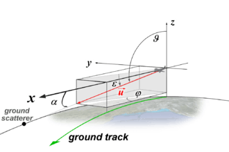
The platform of the radar moves in direction of the x-axis. The radar “looks” with the looking angle θ (or so called off-nadir angle). The angle α between x-axis and the line of sight (LOS) is called cone angle, the angle φ between the x-axis and the projection of the line of sight to the (x; y)-plane is called azimuth angle. Cone- and azimuth angle are related by cosα = cosφ ∙ cosε. On the earth surface the wave comes in at the (nominal ellipsoidal) incident angle β with respect to the vertical axis at this point. (In some publications the incident angle is denominated to as θi.) The antenna illuminates an area, the so-called footprint. The direction of the incoming wave relative to the horizontal plane may be measured also. This angle γ = 90° − β is called grazing angle. The angle ϑ = ε + 90° is used for a mathematical description in a spherical coordinate system.
For the approximation of a flat earth – which is usual for airborne radar with short to medium range – the grazing angle and the depression angle can be assumed to be equal γ = ε and the incident angle is β = 180° – ϑ. The so-called LOS-vector is a unit vector (in the figures shown as a red arrow) pointing from the antenna to a ground scatterer. The variables u, v, w are directional cosines with respect to the x; y; z axes. The variable u is u = cosα with α as the azimuth angle between the line of sight and the x-axis (direction of flight).

Range resolution (across track)
The range resolution (the ability to separate the pixels of the image perpendicular to the direction of flight) of an SLAR depends on the length of the transmitted pulse. At the ground of Earth the range resolution has got an inverse relationship with the depression angle:

- = duration of the (may be compressed in matched receiver) radar pulse
- = speed of light
- = depression angle


The pulse width is typically 0.4 … 1 µs, i.e. = 8 … 200 m. The shorter the pulse width the lower and the higher the range resolution, but the lower the echo signal. This limitation can be overcome using intra-pulse modulation. Using a step-frequency waveform of bandwidth B the range resolution is .


Azimuthal resolution (along track)
The azimuthal resolution (better known to as crossrange resolution) depends on the beamwidth of the radar antenna. It is derived from the ratio of the physical size of the antenna (the real aperture) to the wavelength used. By the spreading of the beam it is also dependent on the slant range.

- = wavelength
- = antenna length (in direction of flight)
- = slant range
- = height of the platform


It is apparent that SLAR antennas as real aperture could not be built large enough to achieve the desired azimuth resolution. In fact, SLAR was never feasible to be used in space because the antennas would be too large and their launch in space too expensive. Synthetic aperture radar refers to a method for improving the azimuth resolution (not range resolution).
See also
External links
- Radar Remote Sensing
- Radartutorial
- "A Sideways Glance" a 1966 Flight article on SLAR