Servo (radio control)
Servos (also RC servos) are small, cheap, mass-produced servomotors or other actuators used for radio control and small-scale robotics.
Most servos are rotary actuators although other types are available. Linear actuators are sometimes used, although it is more common to use a rotary actuator with a bellcrank and pushrod. Some types, originally used as sail winches for model yachting, can rotate continuously.
Construction
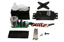
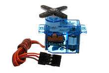
A typical servo consists of a small electric motor driving a train of reduction gears. A potentiometer is connected to the output shaft. Some simple electronics provide a closed-loop servomechanism.
Operation
The position of the output, measured by the potentiometer, is continually compared to the commanded position from the control (i.e., the radio control). Any difference gives rise to an error signal in the appropriate direction, which drives the electric motor either forwards or backwards, and moving the output shaft to the commanded position. When the servo reaches this position, the error signal reduces and then becomes zero, at which point the servo stops moving.
If the servo position changes from that commanded, whether this is because the command changes, or because the servo is mechanically pushed from its set position, the error signal will re-appear and cause the motor to restore the servo output shaft to the position needed.
Almost all modern servos are proportional servos, where this commanded position can be anywhere within the range of movement. Early servos, and a precursor device called an escapement, could only move to a limited number of set positions.
Connection
Radio control servos are connected through a standard three-wire connection: two wires for a DC power supply and one for control, carrying a PWM (pulse-width modulation) signal. Each servo has a separate connection and PWM signal from the radio control receiver. This signal is easily generated by simple electronics, or by microcontrollers such as the Arduino. This, together with their low-cost, has led to their wide adoption for robotics and physical computing.
RC servos use a three-pin 0.1" spacing jack (female) which mates to standard 0.025" square pins. The most common order is signal, +voltage, ground. The standard voltage is 4.8 V DC, however 6 V and 12 V has also been seen for a few servos. The control signal is a digital PWM signal with a 50 Hz frame rate. Within each 20 ms timeframe, an active-high digital pulse controls the position. The pulse nominally ranges from 1.0 ms to 2.0 ms with 1.5 ms always being center of range. Pulse widths outside this range can be used for "overtravel" -moving the servo beyond its normal range. This PWM signal is sometimes (incorrectly) called Pulse Position Modulation (PPM)(e.g. Arduino microcontroller documentation). This arises from confusion in distinguishing between the two general types of PWM: defining value (and hence servo position) by absolute on time; and defining value by the relative percentage of on time versus off time. The first case allows (arbitrarily) widely spaced pulses for multiple servos to share one communication channel (multiplexing) using relatively simple electronics, and is the basis of modern RC servos. The second type is the more traditional usage of PWM (a simple low-pass filter converts a PWM signal into an analog voltage), but there is no need for a different term for the first type, which is sensitive to pulse order but not pulse position.
The servo is controlled by three wires: ground, power, and control. The servo will move based on the pulses sent over the control wire, which set the angle of the actuator arm. The servo expects a pulse every 20 ms in order to gain correct information about the angle. The width of the servo pulse dictates the range of the servo's angular motion.
A servo pulse of 1.5 ms width will typically set the servo to its "neutral" position or 45°, a pulse of 1.25 ms could set it to 0° and a pulse of 1.75 ms to 90°. The physical limits and timings of the servo hardware varies between brands and models, but a general servo's angular motion will travel somewhere in the range of 90° - 120° and the neutral position is almost always at 1.5 ms. This is the "standard pulse servo mode" used by all hobby analog servos.
A hobby digital servo is controlled by the same "standard pulse servo mode" pulses as an analog servo.[1] Some hobby digital servos can be set to another mode that allows a robot controller to read back the actual position of the servo shaft. Some hobby digital servos can optionally be set to another mode and "programmed", so it has the desired PID controller characteristics when it is later driven by a standard RC receiver.[2]
RC servos are usually powered by the receiver which in turn is powered by battery packs or an electronic speed controller (ESC) with an integrated or a separate battery eliminator circuit (BEC). Common battery packs are either NiCd, NiMH or lithium-ion polymer battery (LiPo) type. Voltage ratings vary, but most receivers are operated at 5 V or 6 V.
Mechanical specification
Manufacturers and distributors of hobby RC servos often use a specific shorthand notation of mechanical properties of the servos. Two figures are typically stated, angular speed of servo shaft rotation and mechanical torque produced on the shaft. Speed is expressed as a time interval that a servo requires in order to rotate the shaft for 60 degree angle. Torque is expressed as weight that can be pulled up by the servo if it hangs from a pulley with a certain radius mounted on the shaft.
For example, if a servo model is described as "0.2sec/2kg", that should be interpreted as "This servo rotates the shaft for 60 degrees in 0.2 seconds, and it is able to pull up 2 kg weight using a 1 cm radius pulley". That is, that particular servo model rotates the shaft with the angular speed of (2 * Pi / 6) / 0.2 sec = 5.2 rad/sec while producing 2 kg * 9.81 m/s^2 = 19.6 N force at 1 cm distance i.e. it produces 19.6 N * 0.01 m = 0.196 Nm torque.
Although not in accordance with either the SI or Imperial unit system, the shorthand notation is in fact quite useful as 60 degrees shaft rotation commands, 1 cm long shaft cranks as well as control rod "forces" in kg range are typical in hobby RC world.
Continuous rotation servos
Continuous rotation servos are servos which do not have a limited travel angle, instead they can rotate continuously. They can be thought of as a motor and gearbox with servo input controls. In such servos the input pulse results in a rotational speed, and the typical 1.5 ms center value is the stop position. A smaller value should turn the servo clockwise and a higher one counterclockwise.
Escapements
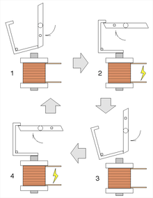
The earliest form of sequential (although not proportional) actuator for radio control was the escapement.[3] Like the device used in clocks, this escapement controls the release of stored energy from a spring or rubber band. Each signal from the transmitter operates a small solenoid that then allows a two- or four-lobed pawl to rotate. The pawl, like a clock, has two pallets so that the pawl can only rotate by one lobe's position, per signal pulse. This mechanism allows a simple keyed transmitter to give sequential control, i.e. selection between a number of defined positions at the model.
A typical four-lobe escapement used for rudder control is arranged so that the first and third positions are "straight ahead", with positions two and four as "left" and "right" rudder. A single pulse from the first straight-ahead position allows it to move to left, or three pulses would select right. A further single pulse returns to straight-ahead.[4] Such a system is difficult to use, as it requires the operator to remember which position the escapement is in, and so whether the next turn requires one or three pulses from the current position. A development of this was the two-lobe pawl, where keying the transmitter continuously (and thus holding the solenoid pallet in place) could be used to select the turn positions with the same keying sequence, no matter what the previous position.[4]
Escapements were low-powered, but light-weight. They were thus more popular for model aircraft than model boats.[3] Where a transmitter and receiver had multiple control channels (e.g., a frequency-keyed reed receiver), then multiple escapements could be used together, one for each channel.[3] Even with single channel radios, a sequence of escapements could sometimes be cascaded. Moving one escapement gave pulses that in turn drove a second, slower speed, escapement.[4] Escapements were disappearing from radio control, in favour of servos, by the early 1970s.[3]
See also
References
- ↑ Society of Robots, "What is the difference between an analog and digital servo?"
- ↑ "Digital Servo Operation and Interface", robosavvy.com basicmicro.com
- 1 2 3 4 Philip Connolly; Vic Smeed (1970). Radio Control Model Boats. Model and Allied Publications. pp. 93–94.
- 1 2 3 Smeed & Connolly 1970, p. 15
External links
| Wikimedia Commons has media related to Servos (radio control). |