Engine balance
Engine balance refers to those factors in the design, production, engine tuning, maintenance and the operation of an engine that benefit from being balanced. Major considerations are:
- Balancing of structural and operational elements within an engine
- Longevity and performance
- Power and efficiency
- Performance and weight/size/cost
- Environmental cost and utility
- Noise/vibration and performance
This article is currently limited to structural and operational balance within an engine in general, and balancing of piston engine components in particular.
Overview
Piston engine balancing is a complicated subject that covers many areas in the design, production, tuning and operation. The engine considered to be well balanced in a particular usage may produce unacceptable level of vibration in another usage for the difference in driven mass and mounting method, and slight variations in resonant frequencies of the environment and engine parts could be big factors in throwing a smooth operation off balance. In addition to the vast areas that need to be covered and the delicate nature, terminologies commonly used to describe engine balance are often incorrectly understood and/or poorly defined not only in casual discussions but also in many articles in respected publications.
Internal combustion piston engines, by definition, are converter devices to transform energy in intermittent combustion into energy in mechanical motion. A slider-crank mechanism is used in creating a chemical reaction on fuel with air (compression and ignition), and converting the energy into rotation (expansion). The intermittent energy source combined with the nature of this mechanism make the engine naturally vibration-prone. Multi-cylinder configuration and many of the engine design elements are reflections of the effort to reduce vibrations through the act of balancing.
This article is organized in six sections:
- lists the balancing elements to establish the basics on the causes of imbalance.
- lists different kinds of vibration as the effects of imbalance.
- discusses the term "Primary balance".
- explains what Secondary balance is, and how the confusing terminologies 'Primary' and 'Secondary' came into popular use.
- goes into engine balance discussions on various multi-cylinder configurations.
- is an introduction to the balancing of 2-cylinder locomotives and includes the wheel hammer effect unique to steam locomotives.
Items to be balanced
There are many factors that can contribute to engine imbalance, and there are many ways to categorize them. The following categories will be used for the purposes of this discussion. In the category descriptions, 'Phase' refers to the timing on the rotation of crankshaft, 'Plane' refers to the location on the crankshaft rotating axis, and 'CG' refers to the center of gravity.
- Mechanical
- Static Balance - Static balance refers to the balancing of weight and the location of CG on moving parts.
- 1. Reciprocating mass - e.g. Piston and connecting rod weight and CG uniformity.
- 2. Rotating mass - e.g. Crank web weight uniformity and flywheel eccentricity (or lack thereof)
- Dynamic Balance - In order for a mass to start moving from rest or change direction, it needs to be accelerated. A force is required to accelerate a mass. According to Newton's 3rd law of motion, there will be a counter force in the opposite direction of equal size. Dynamic balance refers to the balancing of these forces and forces due to friction.
- All accelerations of a mass can be divided into two components in opposite directions. For example, in order for a piston in a single cylinder engine to be accelerated upward, something must receive (support) the downward force, and it is usually the mass of the entire engine that moves downward a bit as there is no counter-moving piston. This means one cause of engine vibration usually appears in two opposing directions. Often the movement or deflection in one direction appears on a moving mass, and the other direction appears on the entire engine, but sometimes both sides appear on moving parts, e.g. a torsional vibration in a crankshaft, or a push-pull cyclic stress in a chain or connecting rod. In other cases, one side is a deflection of a static part, the energy of which is converted into heat and dissipated into the coolant.
- Reciprocating mass - Piston mass needs to be accelerated and decelerated, resisting a smooth rotation of a crankshaft. In addition to the up-down movement of a piston, a connecting rod big end swings left and right and up and down while it rotates. In order to simplify the motion of a crank slider mechanism, the connecting rod/piston assembly is generally divided into two mass groups, a reciprocating mass, and a rotating mass. The big end of the rod is generally said to be rotating while the small end is said to be reciprocating. In truth, however, both ends both reciprocate and rotate.
- 3. Phase balance - e.g. Pistons on 60 or 90° V6 without an offset crankshaft reciprocate with unevenly spaced phases in a crank rotation
- 4. Plane balance - e.g. Boxer Twin pistons travel on two different rotational planes of the crankshaft, which creates forces to rock the engine on Z-axis[note 1]
- Rotating mass
- 5. Phase balance - e.g. Imbalance in camshaft rotating mass can generate a vibration with a frequency equal to once in 2 crank rotations in a 4 cycle engine
- 6. Plane balance - e.g. Boxer Twin crankshaft without counterweights rocks the engine on Z-axis[1]
- 7. Torsional balance - If the rigidity of crank throws on an inline 4 cylinder engine is uniform, the crank throw farthest from the clutch surface (usually called cylinder #1) normally shows the biggest torsional deflection. It is usually impossible to make these deflections uniform across multiple cylinders except on a radial engine. See Torsional vibration
- 8. Static mass - A single cylinder 10 HP engine weighing a ton is very smooth, because the forces that comprise its imbalance in operation must move a large mass to create a vibration. As power to weight ratio is important in the design of an engine, the weight of a crankcase, cylinder block, cylinder head, etc. (i.e. static mass) are usually made as light as possible within the limitations of strength, cost and safety margin, and are often excluded in the consideration of engine balance.
- However, most vibrations of an engine are small movements of the engine itself, and are thus determined by the engine weight, rigidity, location of the CG, and how much its mass is concentrated around the CG. These are crucial factors in engine dynamic balance, which is defined for the whole engine in reciprocal and rotational movements as well as in bending and twisting deflections on the X, Y and Z axis. All of these are important factors in the design of engine mounts and the rigidity of static parts.
- It is important to recognize that some moving masses must be considered a part of static mass depending on the kind of dynamic balance under consideration (e.g. camshaft weight in analyzing the Y-axis[note 1] rotational vibration of an engine).
- Friction
- 9. Slide resistance balance - A piston slides in a cylinder with friction. A ball in a ball bearing also slides as the diameter of inner and outer races are different and the distance of circumference differs from the inside and out. When a ball bearing is used as the main bearing on a crankshaft (which is rarely the case), eccentricity of the cage (race) normally create phase imbalance in slide friction. Friction forces for shell bearings (the most common type of bearings) are dependent upon diameter and width, which determine bearing surface area. This needs to be balanced for the pressure and the rotational speed of the load. Different main bearing sizes on a crankshaft create plane imbalance in slide friction.
- 10. Rolling resistance balance - e.g. A ball in a ball bearing generates friction while rolling in it's cage
- Fluid - Pressure, Flow and Kinetic balance on gas, oil, water, mist, air, etc.
- Torque Balance - Torque here refers to the torque applied to the crankshaft as a form of power generation, which usually is the result of gas expansion. In order for the torque to be generated, that force needs to be countered (supported) in the opposite direction, so engine mounts are essential in power generation, and their design is crucial for a smooth running engine.
- 11. Amount of torque - Normally, the amount of torque generated by each cylinder is supposed to be uniform within a multi-cylinder engine. Often, however, there are small but measurable differences. This irregularity creates torque imbalance in phase and plane.
- 12. Timing/Direction of torque - The maximum force developed on a piston and connecting rod of a cylinder with a fast-burning mixture is exerted at a different angle as compared to a late-igniting or slow-burning cylinder.
- 13. Phase balance - e.g. Combustion in a single cylinder 4 cycle engine occur every 720 degrees of crankshaft rotation, which creates imbalance from one rotation to another.
- 14. Plane balance - Torque is applied to the crankshaft on the crank rotational plane where the connecting rod is located, which are at different distances to the power take off (clutch surface) plane on non-radial multi-cylinder engines.
- Drag - Negative torque that resists the turning of a crankshaft which is caused by fluid elements in an engine.
- Pressure balance - Not only the compression in a cylinder, but also any creation of positive (as in oil pressure) and negative (as in intake manifold) pressure are sources of resistance, which benefit from being uniform.
- 15. Phase balance - e.g. Compression on a single cylinder 4 cycle engine occurs once every 720 degrees in crank rotation phase, which creates imbalance from one rotation to another.
- 16. Plane balance - e.g. Compression on a boxer twin engine occurs at different planes on the crankshaft at different distances to clutch surface. A single plane (single row) radial engine does not have this plane imbalance except for a short mismatch between the power generating plane where the conrods are, and the power take off plane where the propeller is.
- Flow resistance
- 17. Phase balance - e.g. If only one cylinder of a multi-cylinder engine has a restrictive exhaust port, this condition results in increased resistance every 720 degrees on crank rotation on a 4 cycle engine.
- 18. Plane balance - e.g. If only one cylinder of a multi-cylinder inline engine has a restrictive exhaust port, it results in increased resistance on the crank rotational plane where that cylinder/conrod is located.
- 19. Kinetic resistance - Oil, water, vapor, gas and air do have mass, that needs to be accelerated in order to be moved for the operation of an engine. Rolls Royce Merlin and Nakajima Sakae received rear-facing stub exhaust pipes in their development, resulting in a measurable increase in the maximum speed of Supermarine Spitfire, De Havilland Mosquito and Mitsubishi A6M Zero. This is a form of jet propulsion using kinetic energy in the exhaust, implying that the balancing of kinetic resistance arising from fluid components of an engine is not insignificant. Crank webs partially hitting the oil in oil pan (accelerating the oil mass rapidly) could be a big source of vibration.
- 20. Shearing resistance - Metallic parts in an engine are normally designed not to touch each other by being separated by a thin film of oil, but a cam sometimes touches the tappet, and metal bearing surface wears with insufficient oil or with too much / too little clearance. A film of liquid (especially oil) resists being sheared apart, and this resistance could be a source of vibration as experienced on an over-heating engine that is nearing a seizure.
- 21. Thermal - Thermal balance is crucial for the longevity and durability of an engine, but also has a profound effect on many of the above balancing categories. For example, it is common for a longitudinally-mounted inline engines to have the front-most cylinder cooled more than the other cylinders, resulting in the temperature and torque generated on that cylinder less than on other phase and planes. Also, thermal imbalance creates variations in tolerance, creating varied sliding frictions.
Types of vibration
In contrast to the causes of imbalance listed above, effects of imbalance mainly appear as vibration. There are three major types of vibration caused by engine imbalances:
Reciprocating
A single cylinder, 360°-crank parallel twin, or a 180°-crank inline-3 engine normally vibrates up and down because there are no counter-moving piston(s) or there is a mismatch in the number of counter-moving pistons. This is a 3. phase imbalance of reciprocating mass.
Rocking
Boxer engines, 180°-crank parallel twin, 120°-crank inline-3, 90° V4, inline-5, 60° V6 and crossplane 90° V8 normally vibrate rotationally on Z or Y-axis. This is a result of plane imbalances (4., 6., 14. and 16) called the rocking couple.
Four stroke engines with 4 or fewer cylinders normally do not have overlapping power stroke, so tend to vibrate the engine back and forth rotationally on X-axis. Also, multi-cylinder engines with counter moving pistons have a CG height imbalance in a conrod swinging left on the top half of crank rotation, while another swings right on the bottom half, causing the top of the engine to move right while the bottom moves slightly to the left.[note 2] Engines with 13. phase imbalance on torque generation (e.g. 90° V6, 180°-crank inline-3, etc.) show the same kind of rocking vibration on X-axis.
Torsional
Twisting forces on crankshaft cannot be avoided because conrods are normally located at a (often different) distance(s) to the power take-off plane (e.g. clutch surface) on the length of the crankshaft. The twisting vibrations caused by these (7.Torsional imbalance) forces normally cannot be felt outside of an engine, but are major causes of crankshaft failure.
Primary balance
The term "Primary balance" is a major source of confusion in the discussion of engine balance. See the below Secondary (non-sinusoidal) balance section for the underlying meaning and how this terminology came into popular use.
Primary, "first order" or "first harmonic" balance is supposed to indicate the balancing of items that could shake an engine once in every rotation of the crankshaft, i.e. having the frequency equal to one crank rotation. Secondary or "second order" balance should refer to those items with the frequency of twice in one crank rotation, so there could be tertiary (third order), quaternary (fourth order), quinary (fifth order), etc. balances as well.
The term 'harmonic' comes from simple harmonic motion, and is equivalent to the 'sinusoidal' concept described in the section below, thus "secondary harmonic" meant to describe the non-sinusoidal vibration caused by secondary imbalance is incorrect.
A cylinder in 4 cycle engines fires once in two crank rotations, generating forces with the frequency of a half the crankshaft speed, so the concept of "half order" vibrations, is sometimes used when the discussion is on the balances on torque generation and compression.
However, it is somewhat customary to discuss only two categories, primary and secondary, in the discussion of engine balance in which 'Primary' is often meant to be all non-secondary imbalance items lumped together regardless of frequency, and 'Secondary' is meant to be the effects of non-sinusoidal component of piston and conrod motions in slider-crank mechanism as described below.
Secondary (non-sinusoidal) balance
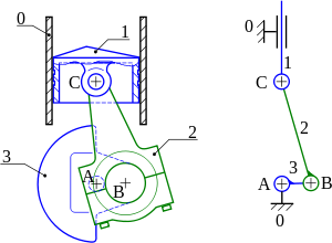
1:Piston
2:Conrod
3:Crankshaft
When the location of B in the drawing on the right is kept at 90° after TDC and if conrod(2) swings right to the vertical position, location of C rises on the arc of the radius 2. The up-down position of the new C location (which is higher than the original C position) is equal to the half-way point of stroke for the small end.
When a crank moves 90 degrees from the top dead centre (TDC) in a single cylinder engine positioned upright, the bigend up-down position is exactly at the half-way point in the stroke, but the conrod is at the most tilted position at this time, and this tilt angle makes the small-end position to be lower than the half-way point in its stroke.
Because the small-end position is lower than the half-way point of the stroke at 90 degrees and at 270 degrees after TDC, the piston moves less distance when the crank rotates from 90 degrees to 270 degrees after TDC than during the crank rotation from 90 degrees before TDC to 90 degrees after TDC. In other words, a piston must travel a longer distance in its reciprocal movement on the top half of the crank rotation than on the bottom half.
Assuming the crank rotational speed to be constant, this means the reciprocating movement of a piston is faster on the top half than on the bottom half of the crank rotation. Consequently, the inertia force created by the mass of a piston (in its acceleration and deceleration) is stronger in the top half of crank rotation than on the bottom half.
So, an ordinary inline 4 cylinder engine with 180 degrees up-down-down-up crank throws may look like cancelling the upward inertia created by the #1-#4 piston pair with the downward inertia of the #2-#3 pair and vice versa, but in fact the upward inertia is always stronger, and the vibration caused by this imbalance is traditionally called the Secondary Vibration.
When a conrod bigend rotates, its up-down movement (as seen from the side of an inline 4 cylinder engine) can be plotted on a graph (with the position on the stroke on Y-axis, rotational position of the crank in degrees on X-axis) with a clean Sine curve, and so this is called the sinusoidal movement. Its left-right changes in position is exactly the same, as it is equivalent to just changing the view point from the side to the top of the engine. However, the up-down position of a conrod small-end (and the piston) does not move in this fashion, as described above, thus is considered not sinusoidal.
The inertia force created by this non-sinusoidal reciprocating motion is equivalent to the mass times the acceleration of change in the position. The simplified change in the up/down position is normally expressed (see Crank (mechanism)) as:

where is the change in up-down position, is the center-to-center conrod length, is the radius of the crank (i.e. a half of stroke), is the change in crank rotational angle from TDC in degrees.


However, the above equation is a sinusoidal motion, and the more precise expression (see Piston motion equations) is:

The difference between the two equations is the effect of conrod tilting angle that lowers the smallend position whenever it is not at TDC or BDC. This means the imbalance is proportional to the ratio of conrod length to stroke, i.e. the longer the conrod in relation to stroke, the less this imbalance becomes. Also, inertia force is created not by a steady speed, but by acceleration and deceleration of mass movement, so the strength is proportional to the square of crankshaft rotational speed, making the imbalance particularly speed sensitive.
This non-sinusoidal motion can mathematically be considered as a combination of two hypothetical sinusoidal motions, one with the frequency equal to the crank rotation (equivalent to the piston motion with infinitely long conrod) which is called the 'primary' component, another with double the frequency[2] (equivalent to the effect of conrod tilting angle that lowers the small-end position from when it is upright), which is the 'secondary' component. Although pistons do not move in the fashion defined by either of these two components, it is easier to analyze the motion as a combination of the two. As this method of considering the piston motion in two components became widely accepted in the field of mathematical analysis, the use of the terms primary and secondary became popular outside of academia without a full grasp on the terminologies and the underlying theory.
The vibration caused by this inertia force (or the difference of its strength between the top and bottom half of crank rotation) is small at lower engine speed, but it grows with the increase in crank rotational speed squared, making it a major problem in high-revving engines.[note 3] Inline 4, inline 6 and 90° V8 engines with flat-plane crankshaft move two pistons always in synch, making the imbalance twice as large (and a half as frequent) as in other configurations that move all pistons in different, evenly spaced, reciprocal phases (e.g. Crossplane inline-four and crossplane V8).
Non-sinusoidal imbalance can almost never be completely cancelled (balanced) with a single-crankshaft multi-cylinder configuration without balancer shafts.[note 4] Boxer engines with many cylinders show the least effect by cancelling all but the (4.) plane imbalance in the cancelling forces.
In designing a balancer for this purpose, it is common to create a sinusoidal force mirroring the hypothetical secondary component with two counter-rotating eccentric weights that rotate at twice the crankshaft speed, as the use of a counter-moving slider-crank as the balancer is less efficient.
Inherent balance
When comparing piston engines with different configurations in the number of cylinders, the V angle, etc., the term "inherent balance" is used. This term often describes just two categories in the above list that are 'inherent' in the configuration, namely, 3. Phase balance on reciprocating mass, and 13. Phase balance on torque generation.
In rare cases when considering a boxer twin, the categories 4. Plane balance on reciprocating mass, 6. Plane balance on rotating mass and sometimes 14. Plane balance on torque generation are included, yet statements like "A flat-8 boxer engine has a perfect inherent balance"[3] ignore these three categories (as well as 16. Plane imbalance on compression) as flat-8 boxer configuration has inherent imbalance in these four categories by having the left and right banks staggered front to back (not positioned symmetrically in plan view) in the same manner as in boxer twin.
"Inherent mechanical balance" further complicates the discussion in the use of the word 'mechanical' by implying to exclude balances on torque generation and compression for some people (as in the above categorization) while not excluding them for others (as they are the results of mechanical interaction among piston, conrod and crankshaft).
While many items on the above category list are not inherent to a configuration of a multi-cylinder engine, it is safe for a meaningful discussion of inherent balance on multi-cylinder engine configurations to include at least the balances on:
- Reciprocating mass (3.Phase and 4.Plane)
- Rotating mass (6.Plane)
- Torque generation (13.Phase and 14.Plane) and
- Compression (15.Phase and 16.Plane)
Two cylinder engines
There are three common configurations in two-cylinder engines: parallel-twin, V-twin, and flat twin.
There are three main types of parallel twins: 360°, 180° & 270°. Secondary imbalance is the strongest on a parallel twin with a 360° crankshaft[4] (that otherwise has the advantage of 13. an evenly spaced firing, and lack of 4. & 6. imbalances), which moves two pistons together. A parallel twin with a 180° crankshaft[5] (that has the disadvantage of 13. uneven firing spacing and strong 4., 6., 14. & 16. imbalance) produces the vibration a half as strong and twice as frequent. The 270° crank, first used on a Yamaha TRX850, gives a firing pattern more regular than a 180° crank, but less regular than a 360° crank. A 270° crank gives optimum secondary engine balance for a parallel twin, and its exhaust note and power delivery resembles those of a 90° V-twin.
In a typical V-twin with a shared crank pin, (e.g.Ducati), the strong vibration of the 360°-crank parallel twin is divided into two different directions and phase separated by the same amount of degrees as in the V angle, with 13. unevenly spaced firing as well as the imbalances 4. Plane imbalance on reciprocating mass, 6. Plane imbalance on rotating mass, 14. Plane imbalance on torque generation and 16. Plane imbalance on compression. These four kinds of imbalance are also known as "rocking couple".

A boxer engine is a type of flat engine in which each of a pair of opposing cylinders is on separate crank throws, offset at 180° to its partner, with 13. an evenly spaced firing. If the pistons could lie on the same crank rotational plane, then the design is inherently balanced for the momentum of the pistons. But since they cannot, the design, despite having a perfect 3. phase balance largely cancelling the non-sinusoidal imbalance, inherently has 4., 6., 14. and 16. imbalances due to the crank pin rotating planes being offset.[6]
.jpg)
This offset, the length of which partly determines the strength of the rocking vibration, is the largest on the parallel twin with a 180° crankshaft, and does not exist on a V or a flat engine that has a shared crank pin with "fork and blade" conrods (e.g. Harley-Davidson V-twin engine. See illustration on right). Other configurations fall in between, depending on the bigend thickness, crank web thickness, and the main bearing width (if they exist in between the throws).
Three cylinder engines
Inline 3 with 120° crankshaft is the most common three cylinder engine. They have 13. evenly spaced firing and perfect 3. phase balance on reciprocating mass, with 4., 6., 14. and 16. imbalances. Just like in a crossplane V8, these first order rocking couples can be countered with heavy counterweights, and the secondary balance is comparable to, or better than an ordinary inline 4 because there are no piston pairs that move together.
This secondary balance advantage is beneficial for making the engine compact, for there is not as much need for longer conrods, which is one of the reasons for the popularity of modern and smooth turbo-charged inline 3 cylinder engines on compact cars. However, the crankshaft with heavy counterweights tend to make it difficult for the engine to be made sporty (i.e. quick revving up and down) because of the strong flywheel effect.
Unlike in a crossplane V8, the bank of three cylinders have evenly spaced exhaust pulse 240° (120° if two stroke) crank rotational angle apart, so a simple three-into-one exhaust manifold can be used for uniform scavenging of exhaust (needed for uniform intake filling of cylinders, which is important for 11. Uniform amount of torque generated and 12. Uniform timing of torque generation), further contributing to the size advantage.
Four cylinder engines
Inline-4, flat-4 and V4 are the common types of four cylinder engine. Normal inline-4 configuration[note 5] has very little rocking couples that often results in smooth middle rpm range, but the secondary imbalance, which is undesirable for high rpm, is large due to two pistons always moving together. Rotational vibration on the X axis, which is often felt during idling, tend to be large because, in addition to the non-overlapping power stroke inherent in engines with 4 or fewer cylinders, the height imbalance from connecting rods centre of gravity swinging left and right[note 2] is amplified due to two connecting rods moving together. Intake and exhaust pulse on ordinary inline-four engines have equal 360° spacing between the front-most and the rear-most cylinders, as well as between the middle two cylinders. So an equal-length (longer-branch) four-into-one exhaust manifold, or two 'Y' pipes each merging exhaust flows from #1 and #4 cylinders, as well as #2 and #3 cylinders are required for evenly spaced exhaust pulse. Older twin-carburetor setup often had each carb throat feeding the front two and the rear two cylinders, resulting in uneven 180°-540°-180°-540° intake pulse on each throat. Modern inline-four engines normally have four equal-length runners to a plenum (which is fed by a throttle at 180° evenly distributed frequency), or four individual throttles (at 720° equal spacing on each throttle).
For in-line 4's there are are 3 types of crankshaft. No counter weights, fully counter weighted (FCW) and semi-counter or half-counter weighted (SCW/HCW). Cranks without counter weights ("bent sticks") were used on in-line 4's up to the mid 1930's for auto-mobiles but are still to be found in agricultural use with attendant problems.[7] Without counter weights an in-line 4 crank is balanced for primary forces, primary and secondary couples but not for secondary forces. Secondary force out balance can not be balanced on the crank, requiring 2 contra-rotating balance shafts running at twice engine speed. These will only be fitted on premium quality cars that demand very smooth running or on large engines in excess of 2.4L where the level of secondary vibration becomes obtrusive. The primary couples bend the crank to a S shape with the deflection increasing with rpm. Without counter weights this deflection causes fatigue and main bearing failures when the deflection exceeds the bearing clearance resulting in rubs. These failures have resulted in a public perception that high rpm is bad for the engine that lingers to this day. FCW cranks have 2 counter weights on each crank throw. SCW cranks have one counter weight on each crank throw, these are on each end of the crank and both sides of the centre main. The counter weights produce moment couples in the crank that counter the primary couple and pull the crank straighter to enable repeated and sustained high rpm with long fatigue and bearing life. The moment couple is proportional to mass x radius of centre of gravity x distance from pivot, the "pivots" being between 1-2 and 3-4. As they are close to the "pivot", the counter weights adjacent to the pivots on a FCW crank only contribute about 1/4 to 1/3 of the moment. The counter weights balance each other completely for primary forces and couples and have no secondary forces/couple. Counter weights do not affect overall engine balance and vibration. There is no benefit in having FCW crank over SCW. The SCW crank is always lighter and allows more rapid engine and vehicle acceleration but may need a heavier flywheel. FCW cranks are used on engines to save space as the piston has to clear the counter weight at bottom dead centre, SCW although only 25-33% larger to obtain the required couple would make the engine taller and the crankcase wider. For automotive use the switch from SCW to FCW is typically around 1.8-2.2L engine capacity. There are a few "hybrid" cranks (Nissan Z22, LD20), these have large counter weights in the SCW position that are as big as the crankcase and piston clearance permits and small counterweights in the remaining positions to produce the required couple. This gives the lightest crank that the crankcase space permits.
Many "tuning" firms producing "billet" cranks misunderstand the design criteria of counter balance weights. They produce cranks that although made from better materials lack sufficient counter weights and deflect more than OEM standard at high rpm. Other "tuning" firms offer "lightening" and "knife edging" of OEM cranks, this is largely at the expense of the counter balance weights. To restore the couple and reduce crankshaft deflection back to OEM spec further work has to undertaken, either installing slugs of high density metal (tungsten) in the counterweights or core drilling the big end journals. For both billet and re-worked OEM cranks if the deflection is greater than OEM spec the results will be poor fatigue and bearing life. For worst cases this may require frequent engine tear downs to replace bearing shells when the crank rubs on the bearing and seasonal replacement of the crank. All of the rotating couple due to crank throw and rotating portion of con-rod and 1/2 the reciprocating couple should be countered. As the balance mass is dependant on the mass of the piston and con-rods if these are changed (for lighter after-market items) then the effect on the couple should be calculated and corrected. Any reputable maker of billet or re-worked cranks should be able to either specify the weights of con-rods and pistons or correct the crank counter weights to suit con-rods and pistons.
Dynamic balance of in-line 4's requires a weight matched set of pistons and con-rods. The con-rods must be matched for rotating mass of the big end taken to be lower 1/3 of the rod and reciprocating mass of little end taken to be the other 2/3. It is not possible to install the rods and pistons on the crank in a dynamic balancing machine. Even if it was, any rotating out of balance would be undetectable due to the secondary out balance. All cranks are balanced at manufacture to OEM spec, this is adequate for domestic use. As performance cars are usually stripped of interior and have harder suspension the vibration from the engine becomes less of a consideration so balancing to better than OEM spec is of little worth. If a crank has been re-worked then it needs re-balancing to OEM spec.
The critical frequency of torsional vibration will change if weights of con-rods, pistons and crank counterweights are changed. This may render the OEM torsional damper ineffective.
Ordinary flat-4 boxer engines[note 6] have excellent secondary balance at the expense of rocking couples due to opposing pistons being staggered (offset front to back). The above-mentioned rotational vibration on the X axis[note 2] is much smaller than in an inline-4 because the pairs of con-rods swinging up and down together move at different centre of gravity heights (different left-right position in this case). Another important imbalance somewhat inherent to boxer-four that is often not dialed out in the design is its irregular exhaust pulse on one bank of two cylinders. Please see flat-four burble explanation part of flat-four engine article on this exhaust requirement similar to the crossplane V8 exhaust peculiarity.
V4 engines come in vastly different configurations in terms of the 'V' angle and crankshaft shapes. Lancia Fulvia V4 engines with narrow V angle have crank pin phase offset corresponding to the V angle, so the firing spacing (phase pattern) is exactly like an ordinary inline-four. But some V4s have irregular firing spacing, and each design needs to be considered separately in terms of all the balancing items.
For example, Honda VFR1200F engine basically is a transversely mounted 76° V4 with a 360° shared-crank-pin crankshaft, but the conrod orientation is an unusual front-rear-rear-front (as opposed to the normal fore-aft-fore-aft) with much wider bore spacing (distance between cylinder centers) on the front bank than on the rear, which results in significantly reduced rocking couples at the expense of wider engine width. Furthermore, the shared crank pin is split and has 28° phase offset, resulting in 256°-104°-256°-104° firing spacing, which is irregular within a 360° crankshaft rotation but evenly distributed from one rotation to another. This compares to a 90° V4 with 180° crankshaft (e.g. Honda RC36 engine) that has 180°-270°-180°-90° firing spaced unevenly within 360 degrees and within 720 degrees of crankshaft rotation.[8]
Five cylinder engines
Inline five cylinder (L5) engine, with crank throws at 72° phase shift to each other, is the common five cylinder configuration. Exceptions are Honda racing V5, and Volkswagen VR5 engine. These typical L5 engines have 13. Evenly spaced firing and perfect 3. Phase balance on reciprocating mass, with 4. Plane imbalance on reciprocating mass, 6. Plane imbalance on rotating mass, 14. Plane imbalance on torque generation, and 16. Plane imbalance on compression. Just like in inline 3 engines above, these first order rocking couples can be countered with heavy counterweights, and the secondary balance is comparable to, or better than an ordinary inline 6 because there are no piston pairs that move together.
Compared to three and four cylinder designs, a major advantage in 4-stroke format is the overlap in power stroke, where the combustion at every 144° of crank rotation ensures a continuous driving torque, which, while not as much noticeable at high rpm, translates to a much smoother idle.
Modern examples such as the 2013 Audi RS3 engine have undersquare design, because the advantage in secondary balance allows it to have longer stroke without sacrificing the higher rpm smoothness, which is desirable for a smaller bore that results in shorter engine length. Honda G20A also with an undersquare design, was originally introduced with a balance shaft driven at the crankshaft speed to counter the wiggling vibration caused by the 6. Plane imbalance on rotating mass, but it evolved into 2.5 Liter G25A with heavier counterweights that does not have the balancer.
Inline six cylinder engines
Inline 6 normally has crank throws at 120° phase shift to each other with two pistons at about equal distance to the center of the engine (#1 and #6 cylinders, #2 and #5, #3 and #4) always moving together, which results in superb plane balance on reciprocating mass (4.) and rotating mass (6.) in addition to the perfect phase balances 3., 5., 13. and 15.. Combined with the overlapping torque generation at every 120° of crankshaft rotation, it often results in a very smooth engine at idle. However, the piston pairs that move together tend to make secondary imbalance strong at high rpm, and the long length configuration can be a cause for crankshaft and camshaft torsional vibration, often requiring a torsional damper. The long length of the engine often calls for a smaller bore and longer stroke for a given cylinder displacement, which is another cause for large secondary imbalance unless designed with otherwise-unnecessary long conrods that increase engine height. Moreover, 4-stroke inline 6 engines inherently have 14. (Plane imbalance on torque generation) and 16. (Plane imbalance on compression), which are typically more or less balanced on V12 and Flat-12 configurations.
In terms of firing spacing, these typical inline 6 are like two inline 3 engines connected in the middle, so the firing interval is evenly distributed within the front three cylinders and within the back three, with equal 240° spacing within the trio and 120° phase shift to each other. So three-into-one exhaust manifolds on the front and on the rear three cylinders, with each of them then connected with a two-into-one pipe results in 120° (240° if not merged in a dual exhaust system) evenly distributed exhaust pulse.

Intake pulse, which is also important to have equal spacing for evenly filling the cylinders with the same volume and mixture of intake charge for 11. (uniform amount of torque) and 12. (uniform timing in torque generation), is formed the same way, so two carburetors or throttle bodies on two one-into-three intake manifolds each on the front and the rear three cylinders (strictly speaking when the three runner lengths are equal) results in evenly spaced intake pulse. Jaguar XK inline 6 had three SU carburettors each serving the front two, middle two and the rear two cylinders in the later models, which resulted in unevenly distributed intake pulse at the front and the rear carburetors (the middle carb gets an evenly spaced pulse at 360° interval). This configuration, while resulting in higher power due to the increased total flow capacity of the carburetors than the earlier evenly-spaced-pulse twin carburetor configuration, required carefully designed balance passages to be created for the intake manifolds, and although there is a theory that uneven filling may have contributed to the later 4.2 Liter version's "rougher running" reputation compared to the legendary 3.4 and 3.8 Liter versions, the more likely source was the considerably heavier pistons on the 4.2 litre version, and the fact that the combustion chambers were offset, because although the bore spacing was changed, the cylinder head chamber spacing was unchanged.
Modern inline six engines with fuel injection (including Diesels) normally have equal length intake runners connecting the intake ports to (often protruding into) a plenum (See Inlet manifold for parts descriptions) to keep intake pulse evenly spaced.
V6 engines

V6 engines with un-split shared crank pin can have equally spaced firing when the V-angle is at 120° (60° or 120° for 2-stroke). However, the 120° bank angle makes the engine rather wide, so production V6 tend to use 60° angle with a crank pin that is offset 60° for the opposing cylinders. As offsetting the crank pin for as much as 60° no longer provides overlap in the diameter of the crank pin, the actual pin is not really an offset 'split' pin, but normally is completely separate in two parts with a thin crank web connecting the two individual pins. This makes the crankshaft structurally weaker, much more so than in the crankshaft with slight offset seen on the Lancia Fulvia V4 with 10.5° to 13° offset, so racing V6 engines from Carlo Chiti-designed 1961 Ferrari 156 engine to Cosworth GBA for Formula One often used the 120° bank angle to avoid this weakness, unless required by the formula as in all the 2014 - 2015 Formula One 1.6 Liter turbo V6 engines that has 90° bank angle according to the regulation.[9]
60° V6 is compact in length, width and height, which is advantageous for rigidity and weight. The short crankshaft length mitigates the torsional vibration problem, and secondary balance is better than in an inline 6 because there is no piston pair that move together. Furthermore, each bank of three cylinders have evenly spaced induction/ignition interval, so the intake/exhaust system advantage is shared with inline 3. However, these advantages come at the price of having plane imbalances on 4. rotating mass, 6. reciprocating mass, 14. torque generation, and 16. compression. Also, the left and the right banks being staggered (for the thickness of a conrod plus the thin crank web) makes the reciprocating mass plane imbalance more difficult to be countered with heavy counterweights than in inline 3, but when the engine and engine mounts are properly designed, it makes a smooth powerplant like Alfa Romeo V6 engines which have counterweighted webs in between the 'split' crank pins that are as thick as crank arms.
90° V6 sometimes were designed like chopping 2 cylinders off common V8 engines to share production tooling (e.g. General Motors 90° V6 engines up to 229 CID with 18° offset crankshaft and uneven firing interval), but newer examples (e.g. Honda Honda C engines that evolved from not having a balancer to the 3.5 liter version with a balance shaft) are dedicated designs with 30° offset crank pins that result in even combustion spacing. Compared to 60° V6, the offset crank pins could have overlap in the diameter of the pin, and the V angle coincides with the angle of mean directions of conrods swinging left and right in each bank. It also shares the four (4., 6., 14. and 16.) plane imbalances and the staggered cylinders, but there is the secondary balance advantage over inline 6 as well.
Flat six engines
Flat six engine with 180° phase offset between opposing cylinder pair, and 120° phase offset among the three pairs (these are called Boxer Six engine) is the common configuration. These 6 cylinder Boxer engines have 14. (Plane imbalance on torque generation) and 16. (Plane imbalance on compression) just like in inline six. As the strength of vibration generated by these imbalances are more or less proportional to engine length, boxer six has the advantage as flat-6 is much shorter than an inline 6 configuration. However, boxer six has additional plane imbalances on rotating mass (4.) and reciprocating mass (6.) due to its left and right banks being staggered front to back, although the offset distance tends to be much smaller in relation to the engine size than in flat-four and flat-twin.
On the other hand, secondary balance is far superior to Straight Six because there are no piston pairs moving together, and is superior to V6 because a large part of secondary imbalance is cancelled in the opposing cylinder pairs except for the front-to-back offset. This makes a boxer six particularly suited for high-revving operation.
Similar to Straight-six, these typical boxer 6 are like two inline 3 engines sharing a crankshaft, so the firing interval is evenly distributed within the three cylinders on the left bank and within the right three, with equal 240° spacing within the trio in a bank and 120° phase shift to each other. So three-into-one exhaust manifolds on the left and on the right three cylinders, with each of them then connected with a two-into-one pipe results in 120° (240° if not merged in dual exhaust) evenly distributed exhaust pulse. Likewise, intake pulse is evenly distributed among the three cylinders on each bank.
Porsche flat six engine is famous for being a successful design for a long production run, with some early examples (911T model) having a crankshaft without counter-weights.
Steam locomotives
This section is an introduction to the balancing of two steam engines connected by driving wheels and axles as assembled in a railway locomotive.
The effects of unbalanced inertias in a locomotive are briefly shown by describing measurements of locomotive motions as well as deflections in steel bridges. These measurements show the need for various balancing methods as well as other design features to reduce vibration amplitudes and damage to the locomotive itself as well as to the rails and bridges. The example locomotive is a simple, non-compound, type with 2 outside cylinders and valve gear, coupled driving wheels and a separate tender. Only basic balancing is covered with no mention of the effects of different cylinder arrangements, crank angles, etc. since balancing methods for 3 and 4 cylinder locomotives can be complicated and diverse.[10] Mathematical treatments can be found in 'further reading'. For example, Dalby's "The Balancing of Engines" covers the treatment of unbalanced forces and couples using polygons. Johnson and Fry both use algebraic calculations.
At speed the locomotive will tend to surge fore-and-aft and nose, or sway, from side to side. It will also tend to pitch and rock. This article looks at these motions that originate from unbalanced inertia forces and couples in the 2 steam engines and their coupled wheels (some similar motions may be caused by irregularities in the track running surface and stiffness). The first two motions are caused by the reciprocating masses and the last two by the oblique action of the con-rods, or piston thrust, on the guide bars.[11]
There are 3 degrees to which balancing may be pursued. The most basic is static balancing of the off-center features on a driving wheel, i.e. the crankpin and its attached parts. In addition, balancing a proportion of the reciprocating parts can be done with additional revolving weight. This weight is combined with that required for the off-center parts on the wheel and this extra weight causes the wheel to be overbalanced resulting in hammer blow. Lastly, because the above balance weights are in the plane of the wheel and not in the plane of the originating unbalance, the wheel/axle assembly is not dynamically balanced. Dynamic balancing on steam locomotives is known as cross-balancing and is 2-plane balancing with the second plane being in the opposite wheel.
A tendency to instability will vary with the design of a particular locomotive class. Relevant factors include its weight and length, the way it is supported on springs and equalizers and how the value of an unbalanced moving mass compares to the unsprung mass and total mass of the locomotive. The way the tender is attached to the locomotive can also modify its behaviour. The resilience of the track in terms of the weight of the rail as well as the stiffness of the roadbed can affect the vibration behaviour of the locomotive.
As well as giving poor human ride quality the rough riding incurrs maintenance costs for wear and fractures in both locomotive and track components.
Sources of unbalance
All the driving wheels have an out-of-balance which is caused by their off-center crank pins and attached components. The main driving wheels have the greatest unbalance since they have the biggest crankpin as well as the revolving portion of the main rod. They also have the valve gear eccentric crank and the back end of the eccentric rod. In common with the linked driving wheels they also have their own portion of the side rod weight. The part of the main rod assigned a revolving motion was originally measured by weighing it supported at each end. A more accurate method became necessary which split the revolving and reciprocating parts based on the position of the center of percussion. This position was measured by swinging the rod as a pendulum.[12] The unbalance in the remaining driving wheels is caused by a crankpin and side rod weight. The side rod weights assigned to each crankpin are measured by suspending the rod on as many scales as there are crankpins or by calculation.
The reciprocating piston/crosshead/main rod/valve motion link is unbalanced and causes a fore-and-aft surging. Their 90 deg separation causes a swaying couple.[13]
Measuring the effects of unbalance
The whole locomotive tends to move under the influence of unbalanced inertia forces. The horizontal motions for unbalanced locomotives were quantified by M. Le Chatelier in France, around 1850, by suspending them on ropes from the roof of a building. They were run up to equivalent road speeds of up to 40 mph and the horizontal motion was traced out by a pencil, mounted on the buffer beam. The trace was an elliptical shape formed by the combined action of the fore-and-aft and swaying motions. The shape could be enclosed in a 5/8" square for one of the unbalanced locomotives and was reduced to a point when weights were added to counter revolving and reciprocating masses.[14]
The effect of vertical out-of-balance, or varying wheel load on the rail, was quantified by Professor Robinson in the U.S. in 1895. He measured bridge deflections, or strains, and attributed a 28% increase over the static value to unbalanced drivers.[15]
The residual unbalance in locomotives was assessed in three ways on the Pennsylvania Railroad testing plant. In particular, 8 locomotives were tested at the Louisiana Purchase Exposition in 1904. The 3 measurements were:
- the critical speed. This was defined as the speed at which the unbalanced reciprocating parts reversed the pull of the locomotive. At higher speeds this motion was damped by throttling oil flow in dashpots. The critical speed varied from 95 rpm for a Baldwin tandem compound to over 310 rpm for a Cole compound Atlantic.
- the horizontal motion at the pilot. As an example, the Baldwin compound Atlantic moved about 0.80" at 65 mph compared with 0.10" for the Cole compound Atlantic.
- a qualitative assessment of the load on the plant supporting wheels. A 0.060" diameter wire was run under the wheels. Measuring the deformed wire gave an indication of the vertical load on the wheel. For example, a Cole compound Atlantic showed little variation from a 0.020" thickness for all speeds up to 75 mph. In contrast, a Baldwin compound Atlanic at 75 mph showed no deformation, which indicated complete lifting of the wheel, for 30 degrees wheel rotation with a rapid return impact, over only 20 degrees rotation, to a no-hammer blow deformation of 0.020" .[16]
Qualitative assessments may be done on a road trip in terms of the riding qualities in the cab. They may not be a reliable indicator of a requirement for better balance as unrelated factors may cause rough riding, such as stuck wedges, fouled equalizers and slack between the engine and tender. Also the position of an out-of-balance axle relative to the locomotive center of gravity may determine the extent of motion at the cab. A. H. Fetters related that on a 4-8-2 the effects of 26,000 lb dynamic augment under the cg did not show up in the cab but the same augment in any other axle would have.[17]
Static balancing of wheels
Balance weights are installed opposite the parts causing the out-of-balance. The only available plane for these weights is in the wheel itself which results in an out-of-balance couple on the wheel/axle assembly. The wheel is statically balanced only.
Static balancing of reciprocating weight
A proportion of the reciprocating weight is balanced with the addition of an extra revolving weight in the wheel, i.e. still only balanced statically. The overbalance causes what is known as hammer blow or dynamic augment, both terms having the same definition as given in the following references. Hammer blow varies about the static mean, alternately adding to and subtracting from it with each wheel revolution.[18] In the United States it is known as dynamic augment, a vertical force caused by a designer's attempt to balance reciprocating parts by incorporating counterbalance in wheels.[19]
The term hammer blow does not describe what takes place very well since the force varies continuously and only in extreme cases when the wheel lifts from the rail for an instant is there a true blow when it comes back down.[20]
Up until about 1923 American locomotives were balanced for static conditions only with as much as 20,000 lb variation in main axle load above and below the mean per revolution from the unbalanced couple.[21] The rough riding and damage led to recommendations for dynamic balancing including defining the proportion of reciprocating weight to be balanced as a proportion of the total locomotive weight, or with Franklin buffer,[22] locomotive plus tender weight.
A different source of varying wheel/rail load, piston thrust, is sometimes incorrectly referred to as hammer blow or dynamic augment although it does not appear in the standard definitions of those terms. It also has a different form per wheel revolution as described later.
As an alternative to adding weights to driving wheels the tender could be attached using a tight coupling that would increase the effective mass and wheelbase of the locomotive. The Prussian State Railways built 2-cylinder engines with no reciprocating balance but with a rigid tender coupling.[23] The equivalent coupling for late American locomotives was the friction-damped radial buffer.[24][25]
Dynamic balancing of wheel/axle assembly
The crankpin-and-rods weight on the wheels is in a plane outside the wheel plane location for the static balance weight. 2-plane, or dynamic, balancing is necessary if the out-of-balance couple at speed needs to be balanced. The second plane used is in the opposite wheel.
2-plane, or dynamic, balancing of a locomotive wheel set is known as cross-balancing.[13] Cross-balancing was not recommended by the American Railway Association until 1931. Up to that time only static balancing was done in America, although builders included cross-balancing for export locomotives when specified. Builders in Europe adopted cross-balancing after Le Chatelier published his theory in 1849.[26]
Determination of acceptable hammer blow
Maximum wheel and axle loads are specified for a particular bridge design so the required fatigue life of steel bridges may be achieved.[27] The axle load will not usually be the sum of the 2 wheel loads because the line of action of the cross balancing will be different in each wheel.[28] With the locomotive's static weight known the amount of overbalance which may be put into each wheel to partially balance the reciprocating parts is calculated.[29] Strains measured in a bridge under a passing locomotive also contain a component from piston thrust. This is neglected in the above calculations for allowable overbalance in each wheel. It may need to be taken into account.[30]
Response of wheel to hammer blow
Since the rotating force alternately reduces the wheel load as well as augmenting it every revolution the sustainable tractive effort at the contact patch drops off once per wheel revolution and the wheels may slip.[31] Whether slipping occurs depends on how the hammer blow compares on all the coupled wheels at the same time.
Excessive hammer blow from high slipping speeds was a cause of kinked rails with new North American 4-6-4s and 4-8-4s that followed the 1934 A.A.R. recommendation to balance 40% of the reciprocating weight.[10]
Out-of-balance inertia forces in the wheel can cause different vertical oscillations depending on the track stiffness. Slipping tests done over greased sections of track showed, in one case, slight marking of the rail at a slipping speed of 165 mph but on softer track severe rail damage at 105 mph.[32]
Piston thrust from connecting rod angularity
The steam engine cross-head sliding surface provides the reaction to the connecting rod force on the crank-pin and varies between zero and a maximum twice during each revolution of the crankshaft.[33]
Unlike hammer blow, which alternately adds and subtracts for each revolution of the wheel, piston thrust only adds to the static mean or subtracts from it, twice per revolution, depending on the direction of motion and whether the locomotive is coasting, or drifting.
In a double-acting steam engine, as used in a railway locomotive, the direction of the vertical thrust on the slide bar is always upwards when running forward. It varies from nothing at the end of stroke to a maximum at half stroke when the angle between the con-rod and crank are greatest.[34] When the crank-pin drives the piston, as when coasting, the piston thrust is downwards. The position of maximum thrust is shown by the increased wear at the middle of the slide bars.[35]
The tendency of the variable force on the upper slide is to lift the machine off its lead springs at half-stroke and ease it down at the ends of stroke. This causes a pitching and, because the maximum up force is not simultaneous for the 2 cylinders it will also tend to roll on the springs.[34]
Similarities with balancing other machinery
The dynamic balancing of locomotive wheels, using the wheels as the balancing planes for out-of-balance existing in other planes, is similar to the dynamic balancing of other rotors such as jet engine compressor/turbine assemblies. Residual out-of-balance in the assembled rotor is corrected by installing balance weights in 2 planes that are accessible with the engine installed in the aircraft. One plane is at the front of the fan and the other at the last turbine stage.[36]
See also
Notes
- 1 2 Crankshaft rotating axis is referred to as the X-axis, the horizontal line perpendicular to it is referred to as the Y-axis, and the up-down line perpendicular to X and Y axis is called the Z-axis (the cylinders in an inline engine are parallel to the z axis.
- 1 2 3 When a conrod swings left on the top half of crank rotation, another swings right on the bottom half, with the conrod CG heights located as much as the piston stroke apart. When the CG is located at different heights, the swing motion to the left cannot cancel the swing motion to the right, and a rotational vibration is introduced.
- ↑ In an early BRM study, a longer conrod design accounted for up to 5% increase in maximum horse power on a 1.5L GP engine due to the energy wasted in the vibration.
- ↑ It is theoretically possible to completely cancel secondary imbalance with unusual flat-4, flat-8, flat-16, etc. boxer configurations where one bank of cylinders are divided equally into two groups, with one group staggered to the front, and the other group staggered to the rear in mating with the opposite bank, but this arrangement leaves a large gap in between the two groups of cylinders, which is not desirable for size and thermal balance points of view.
- ↑ Normal inline-four has up-down-down-up crank throws. See crossplane inline-four for unusual up-left-right-down or similar crank throws.
- ↑ 'Ordinary' means left-right-right-left crank throws.
References
Citations
- ↑ Foale 2007, p. 2, Fig. 2a.
- ↑ Foale 2007, p. 4, Fig. 4. reciprocating forces (piston motion = red, primary = blue, secondary = green).
- ↑ Taylor 1985, p. 299.
- ↑ Foale 2007, p. 6, Fig. 13. 360°-crank parallel twin.
- ↑ Foale 2007, p. 6, Fig. 13. 180°-crank parallel twin.
- ↑ Foale 2007, p. 17, Fig. 14. Plane offset.
- ↑ http://www.sne-journal.org/fileadmin/user_upload/tx_pubdb/102227.sne.24.tn_l.pdf
- ↑ Sagawa, Kentaro, VFR1200F, Real value of the progress (in Japanese), retrieved 2014-02-09
- ↑ Fédération Internationale de l’Automobile (2014-01-23), 2014 FORMULA ONE TECHNICAL REGULATIONS (PDF), Article 5.1.7 on p.21, retrieved 2014-02-27
- 1 2 Jarvis, J. M., The Balancing of the BR Class 9 2-10-0 Locomotives
- ↑ Clark 1855, p. 193.
- ↑ Johnson 2002, p. 256.
- 1 2 Bevan 1945, p. 458
- ↑ Clark 1855, p. 178.
- ↑ Proceedings of the American International Association of Railway Superintendents of Bridges and Buildings, p. 195
- ↑ The Pennsylvania Railroad System at the Louisiana Purchase Exposition - Locomotive Tests and Exhibits, The Pennsylvania Railroad Company, 1905, pp. 109,531,676
- ↑ Fry 1933, p. 444.
- ↑ Bevan 1945, p. 456.
- ↑ Johnson 2002, p. 252.
- ↑ Dalby 1906, p. 102.
- ↑ Fry 1933, p. 431.
- ↑ US 2125326, "Engine-Tender Buffer Mechanism"
- ↑ Garbe, Robert (1908), The Application of Highly Superheated Steam to Locomotives, p. 28
- ↑ Johnson 2002, p. 267.
- ↑ http://www.martynbane.co.uk/modernsteam/tech/radial.htm
- ↑ Fry 1933, p. 411.
- ↑ Dick, Stephen M., Fatigue Loading and Impact Behaviour of Steam Locomotives, Hanson-Wilson
- ↑ Fry 1933, p. 434.
- ↑ Fry 1933, p. 432.
- ↑ Fry 1933, p. 442.
- ↑ Bevan 1945, p. 457.
- ↑ Johnson 2002, p. 265.
- ↑ Ripper, William (1903), Steam Engine Theory And Practice, Longman's Green And Co., fig. 301
- 1 2 Clark 1855, p. 167.
- ↑ Handbook for Railway Steam Locomotive Enginemen, 1998, p. 92, ISBN 0711006288
- ↑ White, J. L.; Heidari, M. A.; Travis, M. H., Experience in Rotor Balancing of Large Commercial Jet Engines, Boeing Commercial Airplane Group, fig .3
Sources
- Swoboda, Bernard (1984), Mécanique des moteurs alternatifs, 331 pages, 1, rue du Bac 75007, PARIS, FRANCE: Editions TECHNIP, ISBN 9782710804581
- Foale, Tony (2007), Some science of balance (pdf), Tony Foale Designs: Benidoleig, Alicante, Spain, archived (PDF) from the original on 2013-12-27, retrieved 2013-11-04
- Taylor, Charles Fayette (1985), The Internal Combustion Engine in Theory and Practice, Vol. 2: Combustion, Fuels, Materials, Design, Massachusetts: The MIT Press, ISBN 0-262-70027-1
- Daniel Kinnear Clark (1855), Railway Machinery, 1st ed., Blackie and Son
- Johnson, Ralph (2002), The Steam Locomotive, Simmons-Boardman
- Fry, Lawford H. (1933), "Locomotive Counterbalancing", Transactions of the American Society of Mechanical Engineers
- Dalby, W. B. (1906), The Balancing of Engines, Edward Arnold, Chapter IV – The Balancing of Locomotives
- Bevan, Thomas (1945), The theory of Machines, Longmans, Green and Co
External links
- Engine smoothness (extensive article).