SCART
|
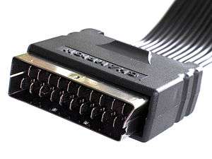
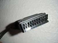
A male SCART connector (21-pin) | |||
| Type | Analogue audio and video connector | ||
|---|---|---|---|
| Production history | |||
| Designer | CENELEC | ||
| Designed | 1970s | ||
| General specifications | |||
| Audio signal | Bi-directional Stereo | ||
| Video signal | Composite (bi-directional), RGB (uni-directional) or S-Video (sometimes bi-directional) or Ypbpr ( component) sometimes with HD capability, but rarely used. | ||
| Pins |
21 (21 wires:RGB/10 wires:CVBS) 10 (10 wires:CVBS) | ||
| Data | |||
| Data signal | D²B and widescreen switching | ||
| Pin out | |||
 | |||
| Female connector seen from the front | |||
| Pin 1 | Audio output (right) | ||
| Pin 2 | Audio input (right) | ||
| Pin 3 | Audio output (left/mono) | ||
| Pin 4 | Audio ground (pins 1, 2, 3 & 6 ground) | ||
| Pin 5 | RGB Blue ground (pin 7 ground) | ||
| Pin 6 | Audio input (left/mono) | ||
| Pin 7 |
RGB Blue up S-Video C down[a] Component PB up[b] | ||
| Pin 8 |
Status & Aspect Ratio up[c]
| ||
| Pin 9 | RGB Green ground (pin 11 ground) | ||
| Pin 10 |
Clock / Data 2[d] Control bus (AV.link) | ||
| Pin 11 |
RGB Green up Component Y up[b] | ||
| Pin 12 | Reserved / Data 1[d] | ||
| Pin 13 | RGB Red ground (pin 15 ground) | ||
| Pin 14 | Usually Data signal ground (pins 8, 10 & 12 ground) | ||
| Pin 15 |
RGB Red up S-Video C up Component PR up[b] | ||
| Pin 16 |
Blanking signal up
| ||
| Pin 17 | Composite video ground (pin 19 & 20 ground) | ||
| Pin 18 | Blanking signal ground (pin 16 ground) | ||
| Pin 19 |
Composite video output S-Video Y output | ||
| Pin 20 |
Composite video input S-Video Y input | ||
| Pin 21 | Shell/Chassis[e] | ||
|
output/input denotes symmetrical links | |||
SCART (from Syndicat des Constructeurs d'Appareils Radiorécepteurs et Téléviseurs – Radio and Television Receiver Manufacturers' Association) is a French-originated standard and associated 21-pin connector for connecting audio-visual (AV) equipment.
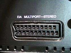
It is also known as Péritel (or Peritelevision) (especially in France), 21-pin EuroSCART (Sharp's marketing term in Asia), Euroconector,[1] EuroAV or EXT. In America, another name is EIA Multiport (an EIA interface).
In Europe, SCART used to be the most common method of connecting AV equipment, and was a standard connector for such devices; it was far less common elsewhere. As it was designed to carry analogue standard-definition content, SCART has become obsolete[2] with the introduction of new digital standards such as HDMI and DisplayPort, which can carry high-definition content and multichannel audio, though it remains commonly used. HDMI-CEC is derived from SCART's AV.link. However, SCART Connection can also support HD signals like 480p, 720p, 1080i, 1080p, if the SCART connection of a device is designed to support YPbPr connection, but this configuration is rare. The same for multichannel audio, but even this configuration remains rare, as it is not standardized .
The official standard for SCART is CENELEC document number EN 50049-1. SCART is sometimes referred to as the IEC 933-1 standard.
Note that there is also a Japanese version of the SCART connector, which is referred to as the Japanese RGB-21 connector, EIAJ TTC-003,[3] or simply JP-21. This version of SCART uses similar signals and the same connector, but it has a different pinout. When using RGB video, the red channel uses the same pins in both standards, so red video with no audio is indicative of mismatching JP-21 SCART with EuroSCART[4]
Origins
The SCART connector first appeared on TVs in 1977. It became compulsory on new TVs sold in France from January 1980,[5][6] and since 1989/1990 in Eastern Europe, such as Poland.
Before SCART was introduced, TVs did not offer a standardised way of inputting signals other than RF antenna connectors, and these differed between countries. Assuming other connectors even existed, devices made by various companies could have different and incompatible standards. For example, a domestic VCR could output a composite video signal through a German-originated DIN-style connector, an American-originated RCA connector, an SO239 connector or a BNC connector.
Usage
The SCART system was intended to simplify connecting AV equipment (including TVs, VCRs, DVD players and games consoles). To achieve this it gathered all of the analogue signal connections into a single cable with a unique connector that made incorrect connections nearly impossible.
The signals carried by SCART include both composite and RGB (with composite synchronisation) video, stereo audio input/output and digital signalling. The standard was extended at the end of the 1980s to support the new S-Video signals. A TV can be awakened from standby mode, and it can automatically switch to appropriate AV channel, when the device attached to it through a SCART connector is turned on. Scart connection was also used for high definition signals like 720i, 720p, 1080i, 1080p with YPbPr connection by some manufacturers, but to the present day this connection is very scarce due to the advent of HDMI.
Daisy chaining
SCART is bi-directional regarding standard composite video and analogue audio. A TV will typically send the antenna audio and video signals to the SCART sockets all the time and watch for returned signals, to display and reproduce them. This allows "transparent" set-top boxes, without any tuner, which just "hook" and pre-process the TV signals. This feature is used for analogue pay TV like Canal Plus and was used for decoding teletext.
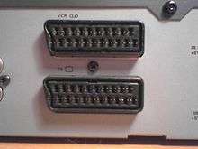
A VCR will often have two SCART sockets, to connect it to the TV ("up", "primary" or "1"), and for video input from a set-top box or other device ("down", "secondary" or "2"). When idle or powered off, VCRs will usually forward the signals from the TV to the set-top decoder and send the processed result back to the TV. When a scrambled show is recorded, the VCR will drive the set-top box from its own tuner and send the unscrambled signals to the TV for viewing or simple recording control. Alternatively, the VCR could use the signals from the TV, in which case it would be inadvisable to change channels on the TV during the recording.
The "down" socket can also be used to connect other devices, such as DVD players or game consoles. As long as all devices have at least one "up" and "down" socket, this allows for connecting a virtually unlimited number of devices to a single SCART socket on the TV. While audio and video signals can travel both "up" to the TV and "down" to devices farther away from the TV, this is not true for RGB (and non-standard YPBPR) signals, which can only travel towards the TV.
"Up" and "down" are conventional. Logically the TV is the last device of the "up" chain-path (stream) and the first device in the "down" chain path. Physically the TV is under the device which sits on its top, hence the name set-top box for the device. Moreover, some sockets' relative position may enforce the belief that the TV is physically the last in the down direction.
Logically, the TV is on top and ends the "up" chain-path, translating the electrical info in optic and audio. From the same logical point of view the info stream, wherever it originates, may need processing such as decrypting (decoding, descrambling) or adding captioning/subtitles. In this case the info stream is sent logically "down" to dedicated function devices. From the last processing device the info stream is sent logically "up" to the TV, through all the chain-path. Another case is when the info stream is sent "down" and not expected to be sent back "up", for example when sent to a recorder.
Closing a loop on either "up" or "down" chain-path may not have useful effects and may create instability.
Direct connections
As Audio and (Composite) Video use the same pins on "up" and "down" connectors (and require a crosslinked cable), it is also possible to connect two devices directly to each other without paying attention to the type of the socket.
However, this no longer works when S-Video signals are used. As straight links (RGB Red and Blue up) were re-purposed to carry chrominance information, the S-Video pinouts are different for "up" and "down" SCART connectors.[7] Further, they are often not fully implemented.
Paying attention to the type of socket is essential when handling component RGB/YPBPR/S-video. Damage can be caused to devices incorrectly connected as follows:
- connecting SCART 1 ("up") from one device to SCART 1 ("up") of another device when both SCARTs are configured for RGB/YPBPR/S-video-up. Pins 7, 11 and 15 are outputs.
- connecting SCART 2 ("down") from one device to SCART 2 ("down") of another device when both SCARTs are configured for S-video-down. Pin 7 is an output.
- connecting SCART 1 ("up") from a device configured RGB/YPBPR, to SCART 2 ("down") of another device configured with S-video-down. Pin 7 is an output.
Damaging pins 7, 11 or 15 may result in yellow, purple or blue/green images, due to the missing blue, green or red components respectively. When using S-video, damaging pin 7 or 15 may result in black-white images due to the missing chroma component ("down" and "up" respectively). Similarly, damaging pins 7 and 15 (PB and PR) while leaving pin 11 (Y) undamaged may result in black-white images when using YPBPR. Damaging more than one of these pins may result in combined effects.
RGB overlays (fast switching)
SCART enables a device to command the TV to very quickly switch between signals, in order to create overlays in the image. In order to implement captioning or subtitles, a SCART set-top box does not have to process and send back a complete new video signal, which would require full decoding and re-encoding of the color information, a signal-degrading and costly process, especially given the presence of different standards in Europe. The box can instead ask the TV to stop displaying the normal signal and display a signal it generates internally for selected image areas, with pixel-level granularity. This can also be driven by the use of a "transparent" color in a teletext page.
Status and aspect ratio (slow switching)
SCART allows a connected device to bring it in and out of standby mode or to switch it to the AV channel. A VCR or other playback device will optimally power on when a cassette is inserted, power on the TV (or switch it to video mode) and then start playing immediately if the cassette's write protection tab is absent. When turned off, the VCR will ask the TV to power off, which it will do if it had been powered on by the VCR's request and if it remained in video mode. Only some TVs will do this—most only implement automatic switching to and from the SCART input.
The same signal can be used by a satellite receiver or set-top box to signal a VCR that it is supposed to start and stop recording ("pin 8 recording"). This configuration usually requires that the VCR be farther from the TV than the source, so the signal usually travels "down".
SCART also supports automatic widescreen switching. This is an extension of the functionality of a pin which previously only indicated to the TV that an external signal should be displayed. Ideally, a widescreen source should offer three operating modes in order to deal with widescreen signals:
- Widescreen, for TVs that are widescreen or capable of otherwise dealing with widescreen images
- Letterbox, which adds blank space (usually black) at the top and bottom of the image to give a 4:3 aspect ratio
- Pan and scan, which crops the image to achieve a 4:3 aspect ratio; only the centre portion is displayed with the sides truncated (as if zoomed into).
In the first case, the widescreen pin allows to indicate the current signal format, which allows widescreen TVs to adjust the image width, and widescreen-capable standard TVs to compress the scan lines of the 576i image vertically to a letterbox shape portion of the picture tube. In the second case, the widescreen SCART signal is never active and the signal source performs the adaptations itself so that the image has always a standard format as a result. Some sources assume that the TV is always capable of widescreen functionality and hence never perform the adaptations. Some sources will not even issue the widescreen signal or maintain it at the same level all the time. Other sources might offer the option of truncating the sides, but not of letterboxing, which requires significantly more processing. Notably, the circuitry of the early widescreen MAC standard decoders (e.g. the Visiopass) could not letterbox. The limitations apply mostly to satellite TVs, while DVD players can always at least letterbox and often zoom.
Data bus
The use of the data pins was not standardised in the original SCART specification, resulting in the use of several different protocols, both proprietary protocols and semi-proprietary protocols based on standards such as D²B.
Some of the most creative usages appeared in analogue satellite receivers. The function of decoding hybrid, time-compressed analogue-digital MAC transmissions into RGB and analogue audio was akin to making a digital receiver out of an analogue one. The D²B pins (10 and 12) were used for communicating with satellite dish positioners and for driving magnetic polarisers, before these became incorporated into LNBs. The daisy-chaining features were used to connect both a Pay TV decoder and a dish positioner/polariser to a single Decoder socket on the receiver.[8]
CENELEC EN 50157-1 introduced AV.link as a standardised protocol to carry advanced control information between devices. It is a single-wire serial data bus and allows carrying remote control information and to negotiate analogue signal types (e.g. RGB). AV.link is also known as nexTViewLink or trade names such as SmartLink, Q-Link or EasyLink. It appears as the Consumer Electronics Control channel in HDMI.
Grundig's earliest SCART-equipped TVs used pin 14 for a signal, not for ground. When using a cable that grounds that pin it becomes impossible to do anything with the TV's built in teletext other than switch it on or off - page selection etc. become impossible.[9]
Multi channel Surround
The data pins, 10, 12, 14, were used by some manufacturers for DOLBY ProLogic, surround and multichannel on their TV sets (some high end models with built in Dolby decoders, and external surround speakers, both CRT, LCD and plasma sets, and only in Europe ( and European versions of Japanese TV Sets and DVD players), and mainly on S/PDIF ), in order to connect a DVD player to the TV set and stream the Dolby and DTS to the surround of the TV set. However, this protocol was rarely used, as it was limited only to a certain manufacturer, and the connections were different from a manufacturer to another, and in some cases, it was only commanded by the pin 8. In this case, it was unusable with RCA to SCART adapters. Also, if a Compatible TV with such connection and a compatible DVD with such connection, but from different manufacturers were interconnected, the surround might not work, and only the stereo sound from the DVD player was available to the TV, because some manufacturers did not use SPDIF, but an own protocol. Also, this connection might be also lost, if the connection of the DVD with the TV was made indirectly (through a VCR in daisy chaining mode, for example), however, some VCR allowed the pass-through of this signals. Some DVD player manufacturers on some models offered SPDIF only on SCART, and an adapter in order to extract the digital audio signal to send it to a home cinema. To the present day this connection remains rare, as HDMI, S/PDIF, and TOSLINK can provide multichannel audio, also some TV sets with Surround built in may have an Optical or S/PDIF INPUT, beside Output.
High Definition
Scart connection was also used, in limited cases, as a high definition connection by using an YPbPr connection over scart by some television and audio video equipment (set top boxes, DVD players, Blu-ray players, etc.) manufacturers. By using an YPBPR connection, SCART could be used for high definition signals, like 720i, 720p, 1080i, 1080p. Some manufacturers were using as Y the video composite connection, while others were using the green connection as Y. With the advent of HDMI, and because of the fact that the connection was not standardized (as was S-video) and limited only to a certain manufacturer, devices supporting high definition channels over scart with YPBPR connection became scarce, if not extinct. In many cases, it was implemented over a RGB scart or CVBS Scart and the YPBPR mode of scart was manually switched. YPbPr became used as an independent connection, and SCART was left only for standard definition content.
Cordset types
The original SCART specification provided for different cable (cordset) types denoted by a key color, but color-coding is rarely used and cables often use different, non-standard configurations.
| Type | Ring color | Pins | Description | Symmetric | |
|---|---|---|---|---|---|
| U | Universal | black | 1–20, 21 | Fully wired cable. | no |
| V | Video only | white | 17–20, 21 | Only composite wires. | yes |
| C | Combined | grey | 1–4, 6, 17–20, 21 | Composite Video and Audio | yes |
| A | Audio only | yellow | 1–4, 6, 21 | Audio | yes |
| B | Bus | green | 10, 12, 21 | Only data connections | 1 |
1 depends on protocol used.
Japanese Counterpart - JP21 Pinout

| Pin | Function | Pin | Function | Pin | Function | Pin | Function |
|---|---|---|---|---|---|---|---|
| 1 | Audio left channel input | 2 | Audio left channel output | 3 | Audio ground | 4 | Audio ground |
| 5 | Audio right channel input | 6 | Audio right channel output | 7 | Video ground | 8 | Video ground |
| 9 | CVBS input | 10 | CVBS output | 11 | AV control input | 12 | Ym input |
| 13 | Red signal ground | 14 | Ground | 15 | Red signal I/O | 16 | Ys input |
| 17 | Green signal ground | 18 | Blue signal ground | 19 | Green signal I/O | 20 | Blue signal I/O |
| 21 | Plug shield |
Notes:
- Audio Input: 0.40 mVrms, > 47K ohms
- Audio Output: 0.40 mVrms, > 10K ohms
- CVBS (Composite Video) in and out: 1 Vp-p, 75 ohms, sync: negative
- Ym Input: Switches RGB to half-brightness, for video overlay (L: < 0.4V, H: > 1V, 75 ohms)
- Ys Input: RGB in/out: (Ground for output, 1V+ for Input (preferred)1))
- All RGB lines: 0.7 Vp-p, 75 ohms[10]
Practical considerations

Nearly all modern DVD players and set-top boxes with SCART sockets can output RGB signal, which offers superior picture quality to composite signal. However, many devices do not have RGB output turned on by default, instead defaulting to composite video — RGB often has to be set up manually in the menu or via switches on the back of the device.

The Nintendo GameCube†, Wii†, Dreamcast, PlayStation, PlayStation 2, PlayStation 3, Xbox and Xbox 360 can output RGB, component video, S-Video, or composite video. These consoles come with the standard composite video connector, but the manufacturers and third parties sell connectors for component video hookup and for RGB SCART hookup. Where the Nintendo GameCube and Xbox automatically switch to the proper mode, the PlayStation 2 must be told via a selection in the system menu whether it is to use YPBPR or RGB video. Also, some versions of legacy consoles such as Sega's Master System, Genesis and Nintendo's SNES are capable of outputting RGB signals.
^ † RGB is only available on PAL region GameCube and Wii consoles, while S-Video is only available on NTSC consoles.[11]
Many older home computers (Amstrad CPC, later ZX Spectrum models, MSX, Commodore Amiga, Atari ST, BBC Micro and Acorn Archimedes, etc.) output RGB with composite sync suitable for SCART use, but most used varying non-standard DIN plugs. Standard-resolution arcade monitors use RGB signals with a composite sync, which is SCART-compatible.
Maximum SCART cable length is estimated to be about 10 to 15 metres without amplification.
Due to the relatively high signal voltages used in SCART, "hot plugging" (connecting or disconnecting devices while they are on) is not recommended. Although there is no risk of personal injury, there is the possibility of damaging electronics within the devices if the connector is inserted improperly. Also, since many TVs are Class II (double-insulated) rather than earthed, the large exposed shield on the SCART connector will be held at approximately half mains voltage if it is plugged into a powered TV with the other end unplugged. If the cable is then plugged into an earthed device with a metal case, inadvertent contact with the SCART cable shield while the earthed device is touched with the other hand can cause a painful electric shock. For this reason the device end of the cable should always be plugged in first and the TV end plugged in last.[12][13][14]
Quality differences exist in SCART cables. While a proper SCART cable uses miniature coaxial cables for the video signals, cheap SCART cables often use plain wires for all signals, resulting in a loss of image quality and greatly reducing the maximum cable length. A common problem on a cheap SCART cable is that a TV outputs a composite video signal from its internal tuner and this is induced or cross-talked onto an incoming video signal due to inadequate or non-existent screening; the result is ghostly images or shimmering superimposed on the incoming signal. To non-destructively verify if a SCART cable uses coaxial cables, unscrew the strain relief at the SCART connector and fold open the plastic shell.
Using higher-quality cables such as those with ribbon cords that have properly shielded coaxial cables inside might help in reducing a 'ghosting' effect, but it does not always completely eliminate it due to various factors. A more permanent method is to remove pin 19 (Video Out) from the SCART plug that is put into the TV, preventing a signal from being broadcast by the TV into the cable, so it cannot cross-talk with the incoming signal.
High Definition signals, like 480p, 720p, 1080i or 1080p can also be supported if SCART supports YPbPr connections. However, devices supporting this connection are scarce. With the advent of HDMI, devices supporting SCART with YPbPr are even scarcer. SCART remains widely used mainly for standard definition content, up to 576i, with CVBS or RGB configuration (some manufacturers still offer S-Video connection over SCART), and sometimes for taking the audio line out signal from TV (or set top box without RCA) to a stereo amplifier or home cinema, however, not all televisions (depending on the manufacturer) and set top boxes can output audio line out on SCART in case of HD Broadcasts or when playing AV content on USB.
Multichannel audio, like DOLBY (like SPDIF connections), may be supported on SCART connection, through data pins 10, 12, 14. However, not all devices are compatible with this standards, therefore it remains rarely used, as there is no standard regarding connection, and it may be different from a manufacturer to another. Some Home Cinema Systems equipped with SCART connection, could play the sound of the TV set by hooking the audio output of he TV'S SCART and sending it to the input pins of the SCART on the home cinema, somehow identical with the HDMI-ARC connection, input-output on the same cable (on some of these home cinemas, this SCART input was selectable), and sometimes with DOLBY, if available on data pins 10, 12,14, but to the present day, this feature is rare, mainly because of the advent on HDMI with ARC compatibility. However, SCART remains common in audio mainly with mono and stereo signals and sometimes DOWNMIX DOLBY 2 Channels, creating somehow a surround effect on the TV Sets speakers, if the TV set is stereo and allows such signals. Also, some TV sets and Players (DVD, Blu-ray, or even set top boxes) can support on scart DOLBY 2 CHANNEL or DOLBY VIRTUAL, but in rare cases.
Blanking and switching
Two pins provide switching signals.
Pin 8, the switch signal pin, carries a DC voltage from the source that indicates the type of video present.
- 0 V–2 V means no signal, or internal bypass
- 4.5 V–7 V (nominal 6 V) means a widescreen (16:9) signal
- 9.5 V–12 V (nominal 12 V) means a normal (4:3) signal
Pin 16, the blanking signal pin, carries a signal from the source that indicates that the signal is either RGB or composite.
- 0 V–0.4 V means composite.
- 1 V–3 V (nominal 1 V) means RGB only.
The original specification defined pin 16 as a high frequency (up to 3 MHz) signal that blanked the composite video. The RGB inputs were always active and the signal 'punches holes' in the composite video. This could be used to overlay subtitles from an external Teletext decoder.
- 0 V–0.4 V means composite with a transparent RGB overlay.
- 1 V–3 V (nominal 1 V) RGB only.
There is no switching signal to indicate S-Video. Some TVs can auto-detect the presence of the S-Video signal but more commonly the S-Video input needs to be manually selected. The same for the rare component YPbPr, which is in many cases implemented over a composite or rgb scart.
Cables
The cables for connecting equipment together have a male plug at each end. Some of the wires such as ground, data, switching and RGB connect to the identical pin number at each end. Others such as audio and video are swapped so that an output signal at one end of the cable connects to an input signal at the other end. The complete list of wires that are swapped is: pins 1 and 2, pins 3 and 6, pins 17 and 18, pins 19 and 20.
SCART leads are available in a wide range of stores in Europe and in specialised stores in North America.
See also
References
- ↑ "Conector SCART (Euroconector)". uvigo.es. Retrieved 17 November 2016. (Spanish)
- ↑ http://www.kabelaanbieding.com/index.php?action=extra&extra=A_scart_info&lang=EN Basic information about SCART
- ↑ http://gamesx.com/wiki/doku.php?id=av:japanese_rgb-21
- ↑ https://www.retrogamingcables.co.uk/euroscart-versus-jp21
- ↑ "La télé des années 80". croque-vacances.com. Archived from the original on April 3, 2009. (French)
- ↑ "Le TI-99/4A et la Presse Informatique". perso.orange.fr/fabrice.montupet. Archived from the original on October 14, 2007. (French)
- ↑ S-Video to SCART signal conversion guide. Archived October 8, 2011, at the Wayback Machine.
- ↑ Based on a Pace Micro Technology Prima analogue receiver manual and a DATCOM AP-500/AP-700 dish positioner manual.
- ↑ Based on a Grundig CUC 3510 service manual.
- ↑ http://gamesx.com/wiki/doku.php?id=av:japanese_rgb-21
- ↑ "Game Console RGB SCART Cable Diagrams". Members.optusnet.com.au. Retrieved 2012-06-15.
- ↑ "Electric shock off aerial coax - DIYnot.com - DIY and Home Improvement". DIYnot.com. Retrieved 2012-06-15.
- ↑ "Guide to preventing shocks from entertainment systems" (pdf). Digital TV Group. Retrieved 15 June 2012.
- ↑ ":: EPE Chat Zone :: Radio Bygones Message Board ::: SCART Shock". Chatzones.co.uk. Retrieved 2012-06-15.
External links
| Wikimedia Commons has media related to SCART. |
- SCART connector pinout and cables schemes
- SCART — hardwarebook.info
- RGB/VGA and SCART
- EuroSCART versus JP21