Fibre Channel electrical interface
The Fibre Channel electrical interface is one of two related standards that can be used to physically interconnect computer devices. The other standard is a Fibre Channel optical interface, which is not covered in this article.
Fibre Channel signal characteristics
Fibre channel electrical signals are sent over a duplex differential interface. This usually consists of twisted-pair cables with a nominal impedance of 75 ohms (single-ended) or 150 ohms (differential). This is a genuine differential signalling system so no ground reference is carried through the cable, except for the shield. Signalling is AC-coupled, with the series capacitors located at the transmitter end of the link.
The definition of the Fibre Channel signalling voltage is complex. Eye-diagrams are defined for both the transmitter and receiver. There are many eye-diagram parameters which must all be met to be compliant with the standard. In simple terms, the transmitter circuit must output a signal with a minimum of 600 mV peak-to-peak differential, maximum 2000 mV peak-to-peak differential. A good signal looks rather like a sine-wave with a fundamental frequency of half the data rate, so 1 GHz for a typical system running at 2 gigabits per second.
The Bit-Error Rate (BER) objective for Fibre Channel systems is 1 in 1012 (1 bit in 1,000,000,000,000 bits). At 2 Gbit/s this equates to seven errors per hour. Therefore, this is a common event and the receiver circuitry must contain error-handling logic. In order to achieve such a low error-rate, jitter "budgets" are defined for the transmitter and cables.
Fibre Channel connector pinouts
There are various Fibre Channel connectors in use in the computer industry. Details of their pinouts are distributed between different official documents. The following sections describe the most common Fibre Channel pinouts with some comments about the purpose of their electrical signals.
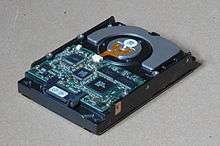
The most familiar Fibre Channel connectors are cable connectors, used for interconnects between initiators and targets (usually disk enclosures). There are also "device connectors" that can be found on Fibre Channel disk-drives and backplanes of enclosures. The device connectors include pins for power and for setting disk options.
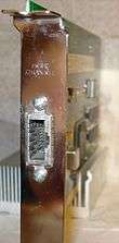
9-pin "DE-9" cable connector
| Pin | Signal name | Comments |
| 1 | +OUT | Fibre channel output |
| 2 | +5V | Optional |
| 3 | Module Fault Detect | Optional |
| 4 | Reserved | |
| 5 | +IN | Fibre channel input |
| 6 | -OUT | Fibre channel output |
| 7 | Output Disable | Optional |
| 8 | GND | Optional, return for pin 2 |
| 9 | -IN | Fibre channel input |
Optional pins 2, 3, 7, and 8 are intended for use with an external optical converter. This is often called a Media Interface Assembly (MIA).
Fibre channel DE-9 connectors often have only the 4 required contacts installed. Note that they are the four outermost contacts i.e. the same as used for Token Ring, this is an easy way to tell a fibre channel cable from an RS-232 cable.
8-pin "HSSDC" cable connector (High Speed Serial Data Connection)
| Pin | Signal name | Comments |
| 1 | +OUT | Fibre channel output |
| 2 | GND | Optional, return for pin 7 |
| 3 | -OUT | Fibre channel output |
| 4 | Module Fault Detect | Optional |
| 5 | Output Disable | Optional |
| 6 | -IN | Fibre channel input |
| 7 | +5V | Optional |
| 8 | +IN | Fibre channel input |
Optional pins 2, 4, 5, and 7 are intended for use with an external optical converter. This is often called a Media Interface Assembly (MIA).
7-pin "HSSDC2" cable connector (High Speed Serial Data Connection)
| Pin | Signal name | Comments |
| 1 | GND | |
| 2 | -OUT | Fibre channel output |
| 3 | +OUT | Fibre channel output |
| 4 | GND | |
| 5 | +IN | Fibre channel input |
| 6 | -IN | Fibre channel input |
| 7 | GND | |
40-pin "SCA-2" disk connector
Although SCA-2 is the official name for this connector, it is often called SCA-40 to distinguish it by its pin count from other similar connectors.
| Pin | Signal name | Comments |
| 1 | -EN Bypass Port 1 | Output driven high when port 1 is operating correctly |
| 2 | +12V | |
| 3 | +12V | |
| 4 | +12V | |
| 5 | -Parallel ESI | Input to allow ESI operation using the SELx pins |
| 6 | -Drive Present | |
| 7 | ACTLED | Output to drive the activity LED cathode |
| 8 | Power Control | |
| 9 | START1 | Input to control spin-up behavior (see the Disk options section) |
| 10 | START2 | Input to control spin-up behavior (see the Disk options section) |
| 11 | -EN Bypass Port 2 | Output driven high when port 2 is operating correctly |
| 12 | SEL6 | Device ID bit 6 / ESI write clock |
| 13 | SEL5 | Device ID bit 5 / ESI read clock |
| 14 | SEL4 | Device ID bit 4 / ESI acknowledge clock |
| 15 | SEL3 | Device ID bit 3 / ESI bit 3 |
| 16 | FLTLED | Output to drive the fault LED cathode |
| 17 | DEVCTRL2 | Input to control interface speed (see the Disk options section) |
| 18 | DEVCTRL1 | Input to control interface speed (see the Disk options section) |
| 19 | +5V | |
| 20 | +5V | |
| 21 | +12V Charge | |
| 22 | GND (12V) | |
| 23 | GND (12V) | |
| 24 | +IN1 | Fibre channel input |
| 25 | -IN1 | Fibre channel input |
| 26 | GND (12V) | |
| 27 | +IN2 | Fibre channel input |
| 28 | -IN2 | Fibre channel input |
| 29 | GND (12V) | |
| 30 | +OUT1 | Fibre channel output |
| 31 | -OUT1 | Fibre channel output |
| 32 | GND (5V) | |
| 33 | +OUT2 | Fibre channel output |
| 34 | -OUT2 | Fibre channel output |
| 35 | GND (5V) | |
| 36 | SEL2 | Device ID bit 2 / ESI bit 2 |
| 37 | SEL1 | Device ID bit 1 / ESI bit 1 |
| 38 | SEL0 | Device ID bit 0 / ESI bit 0 |
| 39 | DEVCTRL0 | Input to control interface speed (see the Disk options section) |
| 40 | +5V CHARGE | |
Disk options
Some of the input signals to a Fibre Channel disk are used to control options, as follows:
START options - if all the disks in an enclosure spin-up immediately on power-on, this can overload the power-supply. Two methods are available to avoid that problem:
| START1 | START2 | Spin-up behaviour |
| 0 | 0 | Automatic, immediate |
| 0 | 1 | Wait for Start Unit SCSI command |
| 1 | 0 | Staggered, delayed depending on loop address |
| 1 | 1 | Reserved |
DEVCTRL options - a disk that has the wrong interface speed can cause serious problems if it is inserted into an enclosure. That problem is avoided by providing three input pins to the disk that define the interface speed at which it will operate:
| DEVCTRLx value | Interface speed |
| 0-4 | Reserved |
| 5 | 4 GB/s |
| 6 | 2 GB/s |
| 7 | 1 GB/s |
External links
- Fibre Channel Physical Interface specification
- Pictures of parallel SCSI connectors
- Pictures of SSA connectors
- Pictures of FC-AL connectors
- Pictures of SAS connectors