Rotary converter
.jpg)
A rotary converter is a type of electrical machine which acts as a mechanical rectifier, inverter or frequency converter.
Rotary converters were used to convert alternating current (AC) to direct current (DC), or DC to AC power, before the advent of chemical or solid state power rectification and inverting. They were commonly used to provide DC power for commercial, industrial and railway electrification from an AC power source.
Rotary converters are still used as frequency converters.
Principles of operation

The rotary converter can be thought of as a motor-generator, where the two machines share a single rotating armature and set of field coils. The basic construction of the rotary converter consists of a DC generator (dynamo) with a set of slip rings tapped into its rotor windings at evenly spaced intervals. When a dynamo is spun the electric currents in its rotor windings alternate as it rotates in the magnetic field of the stationary field windings. This alternating current is rectified by means of a commutator which allows DC current to be extracted from the rotor. This principle is taken advantage of by energizing the same rotor windings with AC power which causes the machine to act as a synchronous AC motor. The rotation of the energized coils excites the stationary field windings producing part of the DC current. The other part is AC current from the slip rings which is directly rectified into DC by the commutator. This makes the rotary converter a hybrid dynamo and mechanical rectifier. When used in this way it is referred to as a synchronous rotary converter or simply a synchronous converter. The AC slip rings also allow the machine to act as an alternator.
The device can be reversed and DC applied to the field and commutator windings to spin the machine and produce AC power. When operated as a DC to AC machine it is referred to as an inverted rotary converter.
One way to envision what is happening in an AC-to-DC rotary converter is to imagine a rotary reversing switch that is being driven at a speed that is synchronous with the power line. Such a switch could rectify the AC input waveform with no magnetic components at all save those driving the switch. The rotary converter is somewhat more complex than this trivial case because it delivers near-DC rather than the pulsating DC that would result from just the reversing switch, but the analogy may be helpful in understanding how the rotary converter avoids transforming all of the energy from electrical to mechanical and back to electrical.
The advantage of the rotary converter over the discrete motor-generator set is that the rotary converter avoids converting all of the power flow into mechanical energy and then back into electrical energy; some of the electrical energy instead flows directly from input to output, allowing the rotary converter to be much smaller and lighter than a motor-generator set of an equivalent power-handling capability. The advantages of a motor-generator set include adjustable voltage regulation which can compensate for voltage drop in the supply network; it also provided complete power isolation, harmonics isolation, greater surge and transient protection, and sag (brownout) protection through increased momentum.
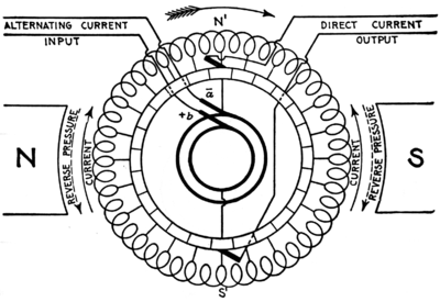
In this first illustration of a single-phase to direct-current rotary converter, it may be used five different ways:[4]
- If the coil is rotated, alternating currents can be taken from the collector rings, and it is called an alternator.
- if the coil is rotated, direct current can be taken from the commutator, and it is called a dynamo.
- If the coil is rotated, two separate currents can be taken from the armature, one providing direct current and the other providing alternating current. Such a machine is called a double current generator.
- If a direct current is applied to the commutator, the coil will begin to rotate as a commutated electric motor and an alternating current can be taken out of the collector rings. This is called an inverted rotary converter (see Inverter).
- If the machine is brought up to synchronous speed by external means and if the direction of the current through the armature has the correct relationship to the field coils, then the coil will continue to rotate in sychronism with the alternating current as a synchronous motor. A direct current can be taken from the commutator. When used this way, it is called a rotary converter.
Applications
A typical use for an AC/DC converter was for railway electrification, where utility power was supplied as alternating current but the trains were designed to work on direct current. Before the invention of mercury arc rectifiers and high-power semiconductor rectifiers, this conversion could only be accomplished using motor-generators or rotary converters.
Around 1900 most machinery and appliances were operated by DC power which was provided by rotary converter substations for residential, commercial and industrial consumption. Rotary converters provided high current DC power for industrial electrochemical processes such as electroplating. Steel mills needed large amounts of on-site DC power for their main roll drive motors. Similarly, paper mills and printing presses required direct current to start and stop their motors in perfect synchronization to prevent tearing the sheet.
Obsolescence
AC to DC synchronous rotary converters were made obsolete by mercury arc rectifiers in the 1930s and later on by semiconductor rectifiers in the 1960s.[5]:54 Some of the original New York City Subway substations using synchronous rotary converters operated until 1999.[5]:12 Compared to the rotary converter, the mercury arc and semiconductor rectifiers did not need daily maintenance, manual synchronizing for parallel operation, nor skilled personnel, and they provided clean DC power. This enabled the new substations to be unmanned, only requiring periodic visits from a technician for inspection and maintenance.
AC replaced DC in most applications and eventually the need for local DC substations diminished along with the need for rotary converters. Many DC customers converted to AC power, and on-site solid-state DC rectifiers were used to power the remaining DC equipment from the AC supply.
Self-balancing dynamo
The self-balancing dynamo is of similar construction to the single- and two-phase rotary converter. It was commonly used to create a completely balanced three-wire 120/240-volt DC electrical supply. The AC extracted from the slip rings was fed into a transformer with a single center-tapped winding. The center-tapped winding forms the DC neutral wire. It needed to be driven by a mechanical power source, such as a steam engine, diesel engine, or electric motor. It could be considered a rotary converter used as a double current generator; the AC current was used to balance the DC neutral wire.
See also
References
- ↑ Hawkins Electrical Guide, 2nd Ed. 1917, p. 1459, fig. 2034
- ↑ Hawkins Electrical Guide, 2nd Ed. 1917, p. 1460, fig. 2035
- ↑ Hawkins Electrical Guide, 2nd Ed. 1917, p. 1461, fig. 2036
- ↑ Hawkins Electrical Guide, 2nd Ed. 1917, p. 1461
- 1 2 Payne, Christopher (2002). New York's Forgotten Substations: The Power Behind the Subway. Princeton Architectural Press. ISBN 978-1568983554.
- Slichter, W.I. (1917). "Converters, Synchronous or Rotary". In Pender, Harold. Handbook for Electrical Engineers. New York: John Wiley & Sons. pp. 279–291.
- Greenberg, Bernard S. (1999). "Rotary Converter Power Technology: AC, DC, and Subway Power." nycsubway.org.
| Wikimedia Commons has media related to Rotary converters. |