Rolls-Royce/Snecma Olympus 593
| Olympus 593 | |
|---|---|
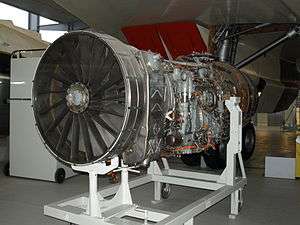 | |
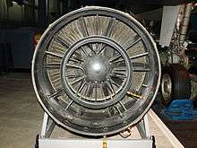
| Preserved Olympus 593 engine at the Imperial War Museum Duxford | |
| Type | Turbojet |
| National origin | United Kingdom/France |
| Manufacturer | Rolls-Royce Limited/Snecma |
| First run | June 1966 |
| Major applications | Concorde |
| Number built | 67 |
| Developed from | Rolls-Royce Olympus |
The Rolls-Royce/Snecma Olympus 593 was an Anglo-French afterburning (reheated) turbojet which powered the supersonic airliner Concorde. It was initially a joint project between Bristol Siddeley Engines Limited (BSEL) and Snecma. It was based on the Bristol Siddeley Olympus 22R engine.[1] Rolls-Royce Limited acquired BSEL in 1966 during development of the engine making BSEL the Bristol Engine Division of Rolls-Royce.[2]
Until regular commercial flights by Concorde ceased, the Olympus turbojet was unique in aviation as the only afterburning turbojet powering a commercial aircraft.
The overall thermal efficiency of the engine in supersonic cruising flight (supercruise) was about 43%, which at the time was the highest figure recorded for any normal thermodynamic machine.[3]
Development
The initial design of the engine was a civil version of the Olympus 22R, redesignated as the 591.[1] The 22R had been designed for sustained (45 minutes) flight at Mach 2.2[3] as the engine for the BAC TSR-2. The 591 was redesigned, being known as the 593, with specification finalised on 1 January 1964.[1] Bristol Siddeley of the UK and Snecma Moteurs of France were to share the project. SNECMA and Bristol Siddeley were also involved in an unrelated joint project, the M45H turbofan.
The early development stages validated the basic design concept, but many studies were required to meet the specifications which included fuel consumption (SFC), engine pressure ratio, weight/size and turbine entry temperature.
Initial studies looked at turbojets and turbofans, but the lower frontal cross-sectional area of turbojets in the end was shown to be a critical factor in achieving superior performance. The competing Russian Tu-144 initially used a turbofan with reheat, but changed to a turbojet without reheat[4] with considerable improvement in performance.
_last_flight.jpg)
Development of the engine and engine accessories was the responsibility of Bristol Siddeley, while BAC was responsible for the variable intake and overall engine installation, and Snecma the exhaust nozzle/thrust reverser/noise attenuation and the afterburner.[5] Britain was to have a larger share in production of the Olympus 593 as France had a larger share in fuselage production. Ground test running of the engines was co-ordinated between Bristol Siddeley, Patchway, the National Gas Turbine Establishment (NGTE), Pystock, UK, and the Centre d'Essais des Propulseurs (CEPr) at Saclay, France.[5]
Increases in aircraft weight during the design phase led to a take-off thrust requirement which could not be met by the engine. The required shortfall of 20% was met with the introduction of partial reheat which was produced by SNECMA.[3]
The Olympus 593B was first run in November 1965. The B (for "Big") was a redesign of the 593D ("D" for "Derivative", i.e., derived from the 22R) which was planned for an earlier smaller Concorde design. Test results from the 593D were used for the design of the B.[6] The B was dropped later from the designation. Snecma used an Olympus 301 in testing scaled models of the nozzle system.[7]
In June 1966, a complete Olympus 593 engine and variable geometry exhaust assembly was first run at Melun-Villaroche, Île-de-France, France. At Bristol, flight tests began using a RAF Avro Vulcan bomber with the engine and its nacelle attached below the bomb-bay. Due to the Vulcan's aerodynamic limitations, the tests were limited to a speed of Mach 0.98 (1,200 km/h). During these tests, the 593 achieved 35,190 lbf (157 kN) thrust, which exceeded the specification for the engine.[8]
In early 1966, the Olympus 593 produced 37,000 lb of thrust with reheat.[9]
In April 1967, the Olympus 593 ran for the first time in a high altitude chamber, at Saclay Île-de-France, France. In January 1968, the Vulcan flying test bed logged 100 flight hours, and the variable geometry exhaust assembly for the Olympus 593 engine was cleared at Melun-Villaroche for flight in the Concorde prototypes.
Concorde prototype 001 made its maiden flight from Toulouse on 2 March 1969. It was captained by André Turcat, chief test pilot of Sud Aviation. Using reheat it lifted off at 205 knots (380 km/h) after a ground run of 4,700 feet (1.4 km).
67 Olympus 593 engines were manufactured.[2]
A quieter, higher thrust version, the Mk 622, was proposed. Reheat was not required and the lower jet velocity reduced the noise from the exhaust.[10] The improved efficiency would have allowed greater range and opened up new routes, particularly across the Pacific as well as transcontinental routes across America. However, the poor sales of Concorde meant that this plan for a Concorde 'B' was not pursued.[11]
Propulsion system design
Engine
The Olympus 593 was a 2-shaft turbojet with reheat. The LP and HP compressors both had 7 stages and were each driven by a single-stage turbine. Due to the high inlet air temperatures at Mach 2 cruise - in excess of 120 degrees C[5] - the compressor drums and blades were made from titanium except for the last 4 HP stages which were Nimonic 90[12] nickel alloy.[13] Nickel alloys were normally only required in the hotter turbine areas but the high temperatures that occur in the last stages of the compressor at supersonic flight speeds dictated its use in the compressor also. Both the HP and LP turbine rotor blades were cooled.
A partial reheat (20% thrust boost)[3] was installed to give the required take-off thrust. It was also used for transonic acceleration from just below Mach 1 up to Mach 1.7; the engine supercruised above that speed and at cruise the thrust through the engine mounts contributed 8% of the thrust from the complete propulsion system.[14]
All major components of the 593 were designed for a life of 25,000 hours, with the exception of the compressor and turbine blades which were designed for a 10,000 hour life.[12] An engine could be changed in one hour, 50 minutes.[15]
Intake
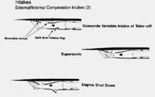
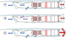
The Concorde's variable geometry intake, designed by BAC, like any jet engine intake, has to deliver the air to the engine at as high pressure as possible (pressure recovery) and with a pressure distribution (distortion) that can be tolerated by the compressor. Poor pressure recovery is an unacceptable loss for the intake compression process and unacceptable distortion causes engine surging (from loss of surge margin). If the engine is an afterburning turbojet the intake also has to supply cooling air for the hot afterburner duct and engine nozzle. Meeting all the above requirements over the relevant parts of the operating envelope was vital for Concorde to become a viable commercial aircraft. They were met with variable geometry and an intake control system that did not compromise the operation of the engine nor the control of the aircraft.
Supersonic pressure recovery is addressed by the number of shock waves that are generated by the intake, the greater the number the higher the pressure recovery. Supersonic flow is compressed or slowed by changes in direction.[16] The Concorde intake front ramps changed the flow direction causing oblique external shocks and isentropic compression in the supersonic flow. The TSR-2 had used a half-cone translating centre-body to change the direction.[17] Subsonic pressure recovery is addressed by removal of the boundary layer (at the ramp bleed slot) and suitable shaping of the subsonic diffuser leading to the engine. The high pressure recovery for the Concorde intake at cruise gave an intake pressure ratio of 7.3:1.[18]
Shock waves gave rise to excessive boundary layer growth on the front ramp. The boundary layer was removed through the ramp bleed slot and bypassed the subsonic diffuser and engine where it would otherwise have caused excessive duct loss and unacceptable distortion at the engine.[19] Since the ramp bleed slot was in the subsonic diffuser, and downstream of the shock system, changes in flow demanded by the engine would be accommodated with corresponding changes in the bleed slot flow without significantly affecting the external shock pattern. Engine flow reductions caused by throttling or shutting down were dealt with by dump door opening.[19]
The dump doors were closed at cruise to prevent loss in thrust since air leaking from the duct does not contribute to the pressure recovery in the intake.[16]
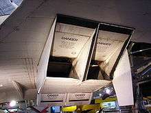
At take-off, since the intake area was dimensioned for cruise, an auxiliary inlet was required to meet the higher engine flow. Distortion of the flow at the engine face also had to be addressed leading to an aerodynamic cascade with the auxiliary door.[19]
Forces from the internal airflow on the intake structure are rearwards (drag) on the initial converging section, where the supersonic deceleration takes place, and forwards on the diverging duct where subsonic deceleration takes place up to the engine entry. The sum of the 2 forces at cruise gave the 63% thrust contribution from the intake part of the propulsion system[14]
In order to achieve the necessary accuracy in the control of the intake ramp and spill positioning, it was found necessary to use a digital signal processor in the Air Intake Control Units. This was developed relatively late in the programme (~1972) by the Electronics and Space Systems division of the British Aircraft Corporation at Filton, Bristol. The Air Intake Control Units ensured the required fuel economy for transatlantic flights. The digital processor also accurately calculated the necessary engine speed scheduling to ensure an adequate surge margin under all engine and airframe operating conditions.
Concorde's Air Intake Control System also pioneered the use of digital data highways (multiplexed serial data buses) which connected the Air Intake Sensor Units that collected aerodynamic data at the nose of the aircraft (total pressure, static pressure, angle of attack and sideslip) and sent it to the Air Intake Control Units located nearer the air intakes using screened, twisted pair cables to replace a much greater weight in aircraft wiring had only analogue signal wiring been used.
The intake control system had the unique ability to keep the powerplants operating correctly and to aid recovery, whatever the pilots, the aircraft and the atmosphere were doing in combination at the time.
The overall pressure ratio for the powerplant at Mach 2.0 cruise at 51,000 ft was about 82:1, with 7.3:1 from the intake and 11.3:1 from the 2 engine compressors.[18] The thermal efficiency with this high pressure ratio was about 43%.[3]
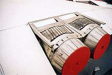
Exhaust nozzle

The variable geometry exhaust nozzle, developed by SNECMA, consisted of two "eyelids" which varied their position in the exhaust flow dependent on the flight regime, for example when fully closed (into the exhaust flow) they acted as thrust reversers, aiding deceleration from landing to taxi speed. In the fully open cruise position, together with engine nozzle, they formed an ejector nozzle to control the expansion of the exhaust. The eyelids formed the divergent passage while the engine exhaust ejected or pumped the secondary flow from the intake ramp bleed slot.
The expanding flow in the diverging section caused a forward thrust force on the exhaust nozzle, its 29% contribution to the overall propulsion system thrust at cruise.[14]
During cruise at Mach 2.05 each Olympus 593 was producing around 10,000 lb of thrust, equivalent to 36,000 horsepower (~27 MW) per engine.[20]
The primary exhaust nozzle and jet pipe were designed for a life of 30,000 hours. The TRA (Thrust Reverser Aft) structure for a life of 40,000 hours.[21]
Variants
- 593 - Original version designed for Concorde
- Thrust : 20,000 lbf (89 kN) dry / 30,610 lbf (136 kN) reheat
- 593-22R - Powerplant fitted to prototypes. Higher performance than original engine due to changes in aircraft specification.
- Thrust : 34,650 lbf (154 kN) dry / 37,180 lbf (165 kN) reheat
- 593-610-14-28 - Final version fitted to production Concorde
- Thrust : 32,000 lbf (142 kN) dry / 38,050 lbf (169 kN) reheat
Engines on display
Preserved examples of the Rolls-Royce/Snecma Olympus 593 are on display at the following museums:
- Brooklands Museum, Weybridge, UK
- Fleet Air Arm Museum, Somerset, UK
- Imperial War Museum Duxford, UK
- M Shed, Bristol, UK
- Royal Air Force Museum Cosford, UK
- London Science Museum, UK
- Intrepid Aerospace Museum, New York
- Museo del Concorde, Mexico
- Yorkshire Air Museum, Elvington, UK
- Sinsheim Auto & Technik Museum, Germany
- National Museum of Flight Scotland, East Fortune, UK
- Musée Aéronautique et Spatial du groupe SAFRAN, Réau, France
In addition to these museums, other sites that display examples of the Olympus 593 include:
- Whittle building, Cranfield University, Cranfield, United Kingdom
- Henriksen Jet Center at the Austin Executive Airport, Texas, USA
- Talbot Laboratory at the University of Illinois at Urbana-Champaign, Illinois, USA[22]
- Aerospace Systems Design Laboratory at the Georgia Institute of Technology, Georgia, USA
Specifications (Olympus 593 Mk 610)
General characteristics
- Type: turbojet
- Length: 4.039 m (13 ft 3 in)
- Diameter: 1.212 m (47.75 in)
- Dry weight: 3,175 kg (7,000 lb)
Components
- Compressor: Axial-flow, 7-stage low-pressure, 7-stage high-pressure
- Combustors: Nickel alloy construction annular chamber, 16 vapourising burners, each with twin outlets
- Turbine: High-pressure single-stage, low-pressure single-stage
- Fuel type: Jet A1
Performance
- Maximum thrust: wet: 169.2 kN (38,050 lbf) dry: 139.4 kN (31,350 lbf)
- Overall pressure ratio: 15.5:1
- Air mass flow: 186 kg/s (410 lb/s)
- Specific fuel consumption: 1.195 lb/(lbf·h) (33.8 g/(kN·s)) cruise / 1.39 lb/(lbf·h) (39 g/(kN·s)) SL (sea level)
- Thrust-to-weight ratio: 5.4:1
See also
- Related development
- Comparable engines
- Related lists
References
- 1 2 3 "Olympus-the first forty years" Alan Baxter, RRHT No15, ISBN 978-1-951171-09-4, p.135
- 1 2
- 1 2 3 4 5 "Not Much of an Engineer" Sir Stanley Hooker An Autobiography, ISBN 1-85310-285-7, p.154
- ↑ "Development of ABE Theory in Russia: Past, Present and Future" Ivanov, Central Institute of Aviation Motors, Moscow 111116
- 1 2 3 http://www.flightglobal.com/pdfarchive/view/1971/1971%20-%200615.html
- ↑ "Aero Engines", Flight: 28, 6 January 1966
- ↑ Flight April 1966
- ↑ Testing of Concorde's engine on a Vulcan
- ↑ "Historical Highlights", Flight International: 14, 17 April 1969
- ↑ http://www.flightglobal.com/pdfarchive/view/1974/1974%20-%200593.html
- ↑
- 1 2 http://www.flightglobal.com/pdfarchive/view/1967/1967%20-%200824.html
- ↑ "Powerplant" concordesst.com
- 1 2 3 "Brian Trubshaw Test Pilot" ISBN 0 7509 1838 1, Appendix VIIIb
- ↑ http://www.flightglobal.com/pdfarchive/view/1971/1971%20-%200613.html
- 1 2 "How Supersonic Inlets Work" J. Thomas Anderson, Copyright Lockheed Martin Corporation, published by Aero Engine Historical Society at "enginehistory.org"
- ↑ Carlo Kopp (June 1997), Profile - The BAC TSR.2, Ausairpower.net, retrieved 19 February 2007,
First published in Australian Aviation,
- 1 2 "Jet Propulsion" Nicholas Cumpsty, ISBN 0 521 59674 2, p.149
- 1 2 3 "Design and Development of an Air Intake for a Supersonic Transport Aircraft" Rettie and Lewis" Journal of Aircraft, November–December 1968 Vol. 5, No. 6
- ↑ https://books.google.co.uk/books?id=HZ18AwAAQBAJ&pg=PT277&lpg=PT277&dq=concorde+cruise+10,000+lb&source=bl&ots=VfhyQpWwk3&sig=-X3mqcQPopY5-RCb2P9ptrXj37M&hl=en&sa=X&ei=cKPwVJSqI87hauSegqgH&ved=0CFMQ6AEwCA#v=onepage&q=concorde%20cruise%2010%2C000%20lb&f=false
- ↑ http://www.flightglobal.com/pdfarchive/view/1971/1971%20-%200614.html
- ↑ "Rolls-Royce Dedicates Concorde's Olympus Engine to AE." AE Illinois, Vol.16 (2014).
- ↑ "Olympus 593". Janes. Archived from the original on 2010-08-06. Retrieved 9 November 2008.
- ↑ untitled
- M. H. Beanland "Development of the Olympus 593" 1969 Flight International
External links
| Wikimedia Commons has media related to Rolls-Royce/Snecma Olympus 593. |
- "Four Olympus Engines will Propel Concorde ..." a 1965 advertisement for the Olympus in Flight
- "Olympus for Concorde" a 1966 Flight article on the basis of the Olympus 593 for Concorde
- Olympian buckets and spades - a 1971 Flight International article on the Olympus 593s Type 28 TRA secondary nozzle/thrust reverser
- "Olympus Flight-testing" a 1972 Flight article on testing the Olympus 593
- Concorde Olympus 593 MK.610 Engines Heritage Concorde