Rolling-element bearing
A rolling-element bearing, also known as a rolling bearing,[1] is a bearing which carries a load by placing rolling elements (such as balls or rollers) between two bearing rings called races. The relative motion of the races causes the rolling elements to roll with very little rolling resistance and with little sliding.
One of the earliest and best-known rolling-element bearings are sets of logs laid on the ground with a large stone block on top. As the stone is pulled, the logs roll along the ground with little sliding friction. As each log comes out the back, it is moved to the front where the block then rolls on to it. It is possible to imitate such a bearing by placing several pens or pencils on a table and placing an item on top of them. See "bearings" for more on the historical development of bearings.
A rolling element rotary bearing uses a shaft in a much larger hole, and cylinders called "rollers" tightly fill the space between the shaft and hole. As the shaft turns, each roller acts as the logs in the above example. However, since the bearing is round, the rollers never fall out from under the load.
Rolling-element bearings have the advantage of a good tradeoff between cost, size, weight, carrying capacity, durability, accuracy, friction, and so on. Other bearing designs are often better on one specific attribute, but worse in most other attributes, although fluid bearings can sometimes simultaneously outperform on carrying capacity, durability, accuracy, friction, rotation rate and sometimes cost. Only plain bearings are used as widely as rolling-element bearings.
Design
There are five types of rolling elements that are used in rolling-element bearings: balls, cylindrical rollers, spherical rollers, tapered rollers, and needle rollers.
Most rolling-element bearings feature cages. The cages reduce friction, wear, and bind by preventing the elements from rubbing against each other. Caged roller bearings were invented by John Harrison in the mid-18th century as part of his work on chronometers.[2]
Typical rolling-element bearings range in size from 10 mm diameter to a few metres diameter, and have load-carrying capacity from a few tens of grams to many thousands of tonnes.
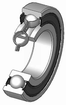
Ball bearing
A particularly common kind of rolling-element bearing is the ball bearing. The bearing has inner and outer races between which balls roll. Each race features a groove usually shaped so the ball fits slightly loose. Thus, in principle, the ball contacts each race across a very narrow area. However, a load on an infinitely small point would cause infinitely high contact pressure. In practice, the ball deforms (flattens) slightly where it contacts each race much as a tire flattens where it contacts the road. The race also yields slightly where each ball presses against it. Thus, the contact between ball and race is of finite size and has finite pressure. Note also that the deformed ball and race do not roll entirely smoothly because different parts of the ball are moving at different speeds as it rolls. Thus, there are opposing forces and sliding motions at each ball/race contact. Overall, these cause bearing drag.
Roller bearings
Cylindrical roller
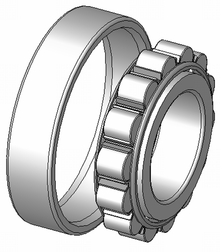
Common roller bearings use cylinders of slightly greater length than diameter. Roller bearings typically have higher load capacity than ball bearings, but a lower capacity and higher friction under loads perpendicular to the primary supported direction. If the inner and outer races are misaligned, the bearing capacity often drops quickly compared to either a ball bearing or a spherical roller bearing.
Roller bearings are the earliest known type of rolling-element-bearing, dating back to at least 40 BC.
Spherical roller
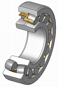
Spherical roller bearings have an outer ring with an internal spherical shape. The rollers are thicker in the middle and thinner at the ends. Spherical roller bearings can thus accommodate both static and dynamic misalignment. However, spherical rollers are difficult to produce and thus expensive, and the bearings have higher friction than an ideal cylindrical or tapered roller bearing since there will be a certain amount of sliding between rolling elements and rings.
Gear bearing
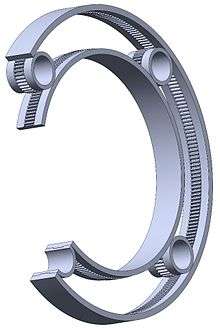
Gear bearing is roller bearing combining to epicyclical gear. Each element of it is represented by concentric alternation of rollers and gearwheels with equality of roller(s) diameter(s) to gearwheel(s) pitch diameter(s). The widths of conjugated rollers and gearwheels in pairs are the same. The engagement is herringbone or with the skew end faces to realize efficient rolling axial contact. The downside to this bearing is manufacturing complexity. Gear bearings could be used, for example, as efficient rotary suspension, kinematically simplified planetary gear mechanism in measuring instruments and watches.
Tapered roller
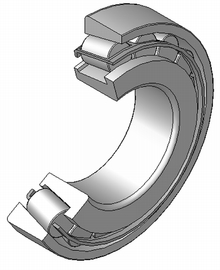
Tapered roller bearings use conical rollers that run on conical races. Most roller bearings only take radial or axial loads, but tapered roller bearings support both radial and axial loads, and generally can carry higher loads than ball bearings due to greater contact area. Tapered roller bearings are used, for example, as the wheel bearings of most wheeled land vehicles. The downsides to this bearing is that due to manufacturing complexities, tapered roller bearings are usually more expensive than ball bearings; and additionally under heavy loads the tapered roller is like a wedge and bearing loads tend to try to eject the roller; the force from the collar which keeps the roller in the bearing adds to bearing friction compared to ball bearings.
Needle roller
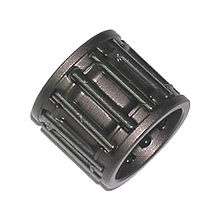
Needle roller bearings use very long and thin cylinders. Often the ends of the rollers taper to points, and these are used to keep the rollers captive, or they may be hemispherical and not captive but held by the shaft itself or a similar arrangement. Since the rollers are thin, the outside diameter of the bearing is only slightly larger than the hole in the middle. However, the small-diameter rollers must bend sharply where they contact the races, and thus the bearing fatigues relatively quickly.
CARB toroidal roller bearings
CARB bearings are toroidal roller bearings and similar to spherical roller bearings, but can accommodate both angular misalignment and also axial displacement.[3] Compared to a spherical roller bearing, their radius of curvature is longer than a spherical radius would be, making them an intermediate form between spherical and cylindrical rollers. Their limitation is that, like a cylindrical roller, they do not locate axially. CARB bearings are typically used in pairs with a locating bearing, such as a spherical roller bearing.[3] This non-locating bearing can be an advantage, as it can be used to allow a shaft and a housing to undergo thermal expansion independently.
Toroidal roller bearings were introduced in 1995 by SKF as "CARB bearings".[4] The inventor behind the bearing was the engineer Magnus Kellström.[5]
Configurations
The configuration of the races determine the types of motions and loads that a bearing can best support. A given configuration can serve multiple of the following types of loading.
Thrust loadings
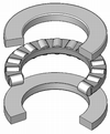
Thrust bearings are used to support axial loads, such as vertical shafts. Common designs are Thrust ball bearings, spherical roller thrust bearings, tapered roller thrust bearings or cylindrical roller thrust bearings. Also non-rolling-element bearings such as hydrostatic or magnetic bearings see some use where particularly heavy loads or low friction is needed.
Radial loadings
Rolling-element bearings are often used for axles due to their low rolling friction. For light loads, such as bicycles, ball bearings are often used. For heavy loads and where the loads can greatly change during cornering, such as cars and trucks, tapered rolling bearings are used.
Linear motion
Linear motion roller-element bearings are typically designed for either shafts or flat surfaces. Flat surface bearings often consist of rollers and are mounted in a cage, which is then placed between the two flat surfaces; a common example is drawer-support hardware. Roller-element bearing for a shaft use bearing balls in a groove designed to recirculate them from one end to the other as the bearing moves; as such, they are called linear ball bearings[6] or recirculating bearings.
Bearing failure
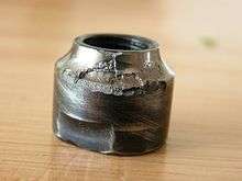
Rolling-element bearings often work well in non-ideal conditions, but sometimes minor problems cause bearings to fail quickly and mysteriously. For example, with a stationary (non-rotating) load, small vibrations can gradually press out the lubricant between the races and rollers or balls (false brinelling). Without lubricant the bearing fails, even though it is not rotating and thus is apparently not being used. For these sorts of reasons, much of bearing design is about failure analysis. Vibration based analysis can be used for fault identification of bearings.[7]
There are three usual limits to the lifetime or load capacity of a bearing: abrasion, fatigue and pressure-induced welding. Abrasion occurs when the surface is eroded by hard contaminants scraping at the bearing materials. Fatigue results when a material becomes brittle after being repeatedly loaded and released. Where the ball or roller touches the race there is always some deformation, and hence a risk of fatigue. Smaller balls or rollers deform more sharply, and so tend to fatigue faster. Pressure-induced welding can occur when two metal pieces are pressed together at very high pressure and they become one. Although balls, rollers and races may look smooth, they are microscopically rough. Thus, there are high-pressure spots which push away the bearing lubricant. Sometimes, the resulting metal-to-metal contact welds a microscopic part of the ball or roller to the race. As the bearing continues to rotate, the weld is then torn apart, but it may leave race welded to bearing or bearing welded to race.
Although there are many other apparent causes of bearing failure, most can be reduced to these three. For example, a bearing which is run dry of lubricant fails not because it is "without lubricant", but because lack of lubrication leads to fatigue and welding, and the resulting wear debris can cause abrasion. Similar events occur in false brinelling damage. In high speed applications, the oil flow also reduces the bearing metal temperature by convection. The oil becomes the heat sink for the friction losses generated by the bearing.
ISO has categorised bearing failures into a document Numbered ISO 15243.
Life calculation
The prediction of bearing life is described in ISO 281[8] and the ANSI/American Bearing Manufacturers Association Standards 9 and 11.[9]
The traditional method to estimate the life of the rolling-element bearings uses the basic life equation:[10]

Where:
- is the 'basic life' (usually quoted in millions of revolutions) for a reliability of 90%, i.e. no more than 10% of bearings are expected to have failed
- is the dynamic load rating of the bearing, quoted by the manufacturer
- is the equivalent dynamic load applied to the bearing
- is a constant: 3 for ball bearings, 4 for pure line contact and 3.33 for roller bearings


Basic life or is the life that 90% of bearings can be expected to reach or exceed.[8] The median or average life, sometimes called Mean Time Between Failure (MTBF), is about five times the calculated basic rating life.[10] Several factors, the 'ASME five factor model',[11] can be used to further adjust the life depending upon the desired reliability, lubrication, contamination, etc.
The major implication of this model is that bearing life is finite, and reduces by a cube power of the ratio between design load and applied load. This model was developed in 1924, 1947 and 1952 work by Arvid Palmgren and Gustaf Lundberg in their paper Dynamic Capacity of Rolling Bearings.[11][12] The model dates from 1924, the values of the constant from the post-war works. Higher values may be seen as both a longer lifetime for a correctly-used bearing below its design load, or also as the increased rate by which lifetime is shortened when overloaded.
This model was recognised to have become inaccurate for modern bearings. Particularly owing to improvements in the quality of bearing steels, the mechanisms for how failures develop in the 1924 model are no longer as significant. By the 1990s, real bearings were found to give service lives up to 14 times longer than those predicted.[11] An explanation was put forward based on fatigue life; if the bearing was loaded to never exceed the fatigue strength, then the Lundberg-Palmgren mechanism for failure by fatigue would simply never occur.[11] This relied on homogeneous vacuum-melted steels, such as AISI 52100, that avoided the internal inclusions that had previously acted as stress risers within the rolling elements, and also on smoother finishes to bearing tracks that avoided impact loads.[9] The constant now had values of 4 for ball and 5 for roller bearings. Provided that load limits were observed, the idea of a 'fatigue limit' entered bearing lifetime calculations: if the bearing was not loaded beyond this limit, its theoretical lifetime would be limited only by external factors, such as contamination or a failure of lubrication.
A new model of bearing life was put forward by FAG and developed by SKF as the Ioannides-Harris model.[12][13] ISO 281:2000 first incorporated this model and ISO 281:2007 is based on it.
The concept of fatigue limit, and thus ISO 281:2007, remains controversial, at least in the US.[9][11]
Constraints and trade-offs
All parts of a bearing are subject to many design constraints. For example, the inner and outer races are often complex shapes, making them difficult to manufacture. Balls and rollers, though simpler in shape, are small; since they bend sharply where they run on the races, the bearings are prone to fatigue. The loads within a bearing assembly are also affected by the speed of operation: rolling-element bearings may spin over 100,000 rpm, and the principal load in such a bearing may be momentum rather than the applied load. Smaller rolling elements are lighter and thus have less momentum, but smaller elements also bend more sharply where they contact the race, causing them to fail more rapidly from fatigue. Maximum rolling-element bearing speeds are often specified in 'nDm', which is the product of the mean diameter (in mm) and the maximum RPM. For angular contact bearings nDms over 2.1 million have been found to be reliable in high performance rocketry applications.[14]
There are also many material issues: a harder material may be more durable against abrasion but more likely to suffer fatigue fracture, so the material varies with the application, and while steel is most common for rolling-element bearings, plastics, glass, and ceramics are all in common use. A small defect (irregularity) in the material is often responsible for bearing failure; one of the biggest improvements in the life of common bearings during the second half of the 20th century was the use of more homogeneous materials, rather than better materials or lubricants (though both were also significant). Lubricant properties vary with temperature and load, so the best lubricant varies with application.
Although bearings tend to wear out with use, designers can make tradeoffs of bearing size and cost versus lifetime. A bearing can last indefinitely—longer than the rest of the machine—if it is kept cool, clean, lubricated, is run within the rated load, and if the bearing materials are sufficiently free of microscopic defects. Note that cooling, lubrication, and sealing are thus important parts of the bearing design.
The needed bearing lifetime also varies with the application. For example, Tedric A. Harris reports in his Rolling Bearing Analysis[15] on an oxygen pump bearing in the U.S. Space Shuttle which could not be adequately isolated from the liquid oxygen being pumped. All lubricants reacted with the oxygen, leading to fires and other failures. The solution was to lubricate the bearing with the oxygen. Although liquid oxygen is a poor lubricant, it was adequate, since the service life of the pump was just a few hours.
The operating environment and service needs are also important design considerations. Some bearing assemblies require routine addition of lubricants, while others are factory sealed, requiring no further maintenance for the life of the mechanical assembly. Although seals are appealing, they increase friction, and in a permanently sealed bearing the lubricant may become contaminated by hard particles, such as steel chips from the race or bearing, sand, or grit that gets past the seal. Contamination in the lubricant is abrasive and greatly reduces the operating life of the bearing assembly. Another major cause of bearing failure is the presence of water in the lubrication oil. Online water-in-oil monitors have been introduced in recent years to monitor the effects of both particles and the presence of water in oil and their combined effect.
Designation
Metric rolling-element bearings have alphanumerical designations, defined by ISO 15, to define all of the physical parameters. The main designation is a seven digit number with optional alphanumeric digits before or after to define additional parameters. Here the digits will be defined as: 7654321. Any zeros to the left of the last defined digit are not printed; e.g. a designation of 0007208 is printed 7208.[16]
Digits one and two together are used to define the inner diameter (ID), or bore diameter, of the bearing. For diameters between 20 and 495 mm, inclusive, the designation is multiplied by five to give the ID; e.g. designation 08 is a 40 mm ID. For inner diameters less than 20 the following designations are used: 00 = 10 mm ID, 01 = 12 mm ID, 02 = 15 mm ID, and 03 = 17 mm ID. The third digit defines the "diameter series", which defines the outer diameter (OD). The diameter series, defined in ascending order, is: 0, 8, 9, 1, 7, 2, 3, 4, 5, 6. The fourth digit defines the type of bearing:[16]
- 0. Ball radial single-row
- 1. Ball radial spherical double-row
- 2. Roller radial with short cylindrical rollers
- 3. Roller radial spherical double-row
- 4. Roller needle or with long cylindrical rollers
- 5. Roller radial with spiral rollers
- 6. Ball radial-thrust single-row
- 7. heavy vehicle bearings prepared
- 7. Roller tapered
- 8. Ball thrust, ball thrust-radial
- 9. Roller thrust or thrust-radial
The fifth and sixth digit define structural modifications to the bearing. For example, on radial thrust bearings the digits define the contact angle, or the presence of seals on any bearing type. The seventh digit defines the "width series", or thickness, of the bearing. The width series, defined from lightest to heaviest, is: 7, 8, 9, 0, 1 (extra light series), 2 (light series), 3 (medium series), 4 (heavy series). The third digit and the seventh digit define the "dimensional series" of the bearing[16][17]
There are four optional prefix characters, here defined as A321-XXXXXXX (where the X's are the main designation), which are separated from the main designation with a dash. The first character, A, is the bearing class, which is defined, in ascending order: C, B, A. The class defines extra requirements for vibration, deviations in shape, the rolling surface tolerances, and other parameters that are not defined by a designation character. The second character is the frictional moment (friction), which is defined, in ascending order, by a number 1–9. The third character is the radial clearance, which is normally defined by a number between 0 and 9 (inclusive), in ascending order, however for radial-thrust bearings it is defined by a number between 1 and 3, inclusive. The fourth character is the accuracy ratings, which normally are, in ascending order: 0 (normal), 6X, 6, 5, 4, T, and 2. Ratings 0 and 6 are the most common; ratings 5 and 4 are used in high-speed applications; and rating 2 is used in gyroscopes. For tapered bearings, the values are, in ascending order: 0, N, and X, where 0 is 0, N is "normal", and X is 6X.[16]
There are five optional characters that can defined after the main designation: A, E, P, C, and T; these are tacked directly onto the end of the main designation. Unlike the prefix, not all of the designations must be defined. "A" indicates an increased dynamic load rating. "E" indicates the use of a plastic cage. "P" indicates that heat-resistant steel are used. "C" indicates the type of lubricant used (C1–C28). "T" indicates the degree to which the bearing components have been tempered (T1–T5).[16]
While manufacturers follow ISO 15 for part number designations on some of their products, it is common for them to implement proprietary part number systems that do not correlate to ISO 15.[18]
See also
References
- ↑ ISO 15
- ↑ Sobel, Dava (1995). Longitude. London: Fourth Estate. p. 103. ISBN 0-00-721446-4.
A novel antifriction device that Harrison developed for H-3 survives to the present day - ...caged ball bearings.
- 1 2 {{ |title=CARB toroidal roller bearings |publisher=SKF |url=http://www.skf.com/group/products/bearings-units-housings/roller-bearings/carb-toroidal-roller-bearings/index.html }}
- ↑ "The CARB bearing – a better solution for the front side of drying cylinders" (PDF). SKF. Retrieved 2 December 2013.
- ↑ "CARB - a revolutionary concept" (PDF). SKF. Retrieved 2 December 2013.
- ↑ http://www.mcmaster.com/#catalog/116/1070
- ↑ Slavic, J; Brkovic, A; Boltezar M (December 2011). "Typical bearing-fault rating using force measurements: application to real data.". Journal of Vibration and Control. 17 (14): 2164–2174. doi:10.1177/1077546311399949.
- 1 2 "Rolling bearings -- Dynamic load ratings and rating life". ISO. 2007. ISO281:2007.
- 1 2 3 Erwin V. Zaretsky (August 2010). "In search of a fatigue limit: A critique of ISO standard 281:2007" (PDF). Tribology & Lubrication Technology. Society of Tribologists and Lubrication Engineers (STLE). pp. 30–40.
- 1 2 Daniel R. Snyder, SKF (12 April 2007). "The meaning of bearing life". Machine Design.
- 1 2 3 4 5 "ISO 281:2007 bearing life standard – and the answer is?" (PDF). Tribology & Lubrication Technology. Society of Tribologists and Lubrication Engineers (STLE). July 2010. pp. 34–43.
- 1 2 "ISO Adopts SKF Bearing Life Calculations". eBearing News. 28 June 2006.
- ↑ Ioannides, Stathis; Harris, Ted (1985). "A New Fatigue Life Model for Rolling Bearings". SKF.
- ↑ Design of liquid propellant rocket engines -Dieter K. Huzel and David H.Huang pg.209
- ↑ Harris, Tedric A. (2000). Rolling Bearing Analysis (4th ed.). Wiley-Interscience. ISBN 0-471-35457-0.
- 1 2 3 4 5 Grote, Karl-Heinrich; Antonsson, Erik K. (2009). Springer handbook of mechanical engineering. 10. New York: Springer. pp. 465–467. ISBN 978-3-540-49131-6.
- ↑ Brumbach, Michael E.; Clade, Jeffrey A. (2003), Industrial Maintenance, Cengage Learning, pp. 112–113, ISBN 978-0-7668-2695-3.
- ↑ Renner, Don; Renner, Barbara (1998). Hands on Water and Wastewater Equipment Maintenance. CRC Press. p. 28. ISBN 978-1-56676-428-5.
Further reading
- Johannes Brändlein; Paul Eschmann; Ludwig Hasbargen; Karl Weigand (1999). Ball and Roller Bearings: Theory, Design and Application (3rd ed.). Wiley. ISBN 0-471-98452-3.
External links
| Wikimedia Commons has media related to Rolling element bearings. |
- Technical publication about bearing lubrication
- NASA technical handbook Rolling-Element Bearing (NASA-RP-1105)
- NASA technical handbook Lubrication of Machine Elements (NASA-RP-1126)
- How rolling-element bearings work
- Kinematic Models for Design Digital Library (KMODDL) - Movies and photos of hundreds of working mechanical-systems models at Cornell University. Also includes an e-book library of classic texts on mechanical design and engineering.