Roll bender
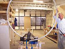
A Roll bender is a mechanical jig having three rollers used to form a metal bar into a circular arc. The rollers freely rotate about three parallel axes, which are arranged with uniform horizontal spacing. Two outer rollers, usually immobile, cradle the bottom of the material while the inner roller, whose position is adjustable, presses on the topside of the material.
Roll bending may be done to both sheet metal and bars of metal. If a bar is used, it is assumed to have a uniform cross-section, but not necessarily rectangular, as long as there are no overhanging contours, i.e. positive draft. Such bars are often formed by extrusion. The material to be shaped is suspended between the rollers. The end rollers support the bottomside of the bar and have a matching contour (inverse shape) to it in order to maintain the cross-sectional shape. Likewise, the middle roller is forced against the topside of the bar and has a matching contour to it.[1]
Operation
After the bar is initially inserted into the jig, the middle roller is manually lowered and forced against the bar with a screw arrangement. This causes the bar to undergo both plastic and elastic deformation. The portion of the bar between the rollers will take on the shape of a cubic polynomial, which approximates a circular arc.[2] The rollers are then rotated moving the bar along with them. For each new position, the portion of the bar between the rollers takes on the shape of a cubic modified by the end conditions imposed by the adjacent sections of the bar. When either end of the bar is reached, the force applied to the center roller is incrementally increased, the roller rotation is reversed and as the rolling process proceeds, the bar shape becomes a better approximation to a circular arc, gradually, for the number of passes required to bring the arc of the bar to the desired radius.
Plastic and elastic deformation

The plastic deformation of the bar is retained throughout the process. However, the elastic deformation is reversed as a section of bar leaves the area between the rollers. This “spring-back” needs to be compensated in adjusting the middle roller to achieve a desired radius. The amount of spring back depends upon the elastic compliance (inverse of stiffness) of the material relative to its ductility. Aluminum alloys, for example, tend to have high ductility relative to their elastic compliance, whereas steel tends to be the other way around. Therefore aluminum bars are more amenable to bending into an arc than are steel bars.
See also
References
- ↑ Todd, Robert H.; Allen, Dell K.; Alting, Leo (1994), Manufacturing Processes Reference Guide, Industrial Press Inc., pp. 300–304, ISBN 0-8311-3049-0.
- ↑ Groover, Mikell P. (2010). Fundamentals of Modern Manufacturing: Materials, Processes, and Systems. John Wiley & Sons. p. 472.