Ring modulator


A Ring modulator is an electronic device for ring modulation, used for amplitude modulation or frequency mixing,
Circuit description
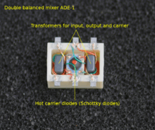
The ring modulator includes an input stage, a ring of four diodes excited by a carrier signal, and an output stage. The input and output stages typically include transformers with centre-taps towards the diode ring. It is important to note that while the diode ring has some similarities to a bridge rectifier the diodes in a ring modulator all point in the same clockwise or counter-clockwise direction.
A particular elegance of the ring modulator is that it is bidirectional: the signal flow can be reversed allowing the same circuit with the same carrier to be used either as a modulator or demodulator, for example in low-cost radio transceivers.
Operation
The carrier, which alternates between positive and negative current, at any given time, makes one pair of diodes conduct, and reverse-biases the other pair. The conducting pair carry the signal from the left transformer secondary to the primary of the transformer at the right. If the left carrier terminal is positive, the top and bottom diodes conduct. If that terminal is negative, then the "side" diodes conduct, creating a polarity inversion between the transformers.
Ring modulators frequency mix or heterodyne two waveforms, and output the sum and difference of the frequencies present in each waveform. Multiplication in the time domain is the dual of convolution in the frequency domain, so the output waveform contains the sum and difference of the input spectral components. For the basic case where two sine waves of frequencies fcarrier and fvoice are multiplied, two new sine waves are created, one at fcarrier + fvoice and the other at fcarrier - fvoice.
In a ring modulator - being a switching modulator - the carrier signal is ideally a square wave, whose Fourier expansion contains the fundamental and a series of reducing-amplitude odd harmonics:
C(t) = sin(fct) + 1/3sin(3fct) + 1/5sin(5fct) + 1/7sin(7fct) + ...
In frequency terms:
C = fc + 1/3 3fc + 1/5 5fc + 1/7 7fc + ...
When the carrier frequency is at least twice the maximum frequency of the modulating signal V(t) then the result is a series of duplicates of V(t) at increasing regions of the frequency spectrum. [1] When the carrier is less than twice the upper frequency of the signal then the resulting output signal conains spectral components from both the signal and the carrier that combine in the time domain. For example, let V(t) represent a sine wave at 100 Hz, and the carrier C(t) be an ideal square wave at 300 Hz. The output will then include sine waves at 100±300 Hz, 100±900 Hz, 100±1500 Hz, 100±2100 Hz, etc., at decreasing amplitudes according to the Fourier expansion of the carrier square wave.
Because the output contains neither the individual voice or carrier components the ring modulator is said to be a double-balanced mixer, [2] where both input signals are suppressed (not present in the output) - the output is composed entirely of the sum of the products of the frequency components of the two inputs.
Limitations
Any DC component of the carrier will degrade the suppression of the carrier and thus in radio applications the carrier is typically transformer- or capacitor-coupled; in low frequency (e.g., audio) applications the carrier may or may not be desired in the output. [3]
Imperfections in the diodes and transformers introduce artefacts of the two input signals. In practical ring modulators this leakage can be reduced by introducing opposing imbalances (e.g., variable resistors or capacitors).
Refinements
The original Cowan patent describes a circuit with a ring of four diodes. Later implementations use FETs as the switching elements.
History
The ring modulator was invented by Frank A. Cowan in 1934 and patented in 1935[4] as an improvement on the invention of Clyde R. Keith at Bell Labs.[5] The original application was in the field of analogue telephony for frequency-division multiplexing for carrying multiple voice signals over telephone cables. It has since been applied to a wider range of uses, such as voice inversion, radio transceivers, and electronic music.
Applications
Analogue telephone systems
The original application of the ring modulator was for combining multiple analogue telephone voice channels into a single wideband signal to be carried on a single cable using frequency-division multiplexing.
Early attempts at securing analogue telephone channels used ring modulators to modify the spectrum of the audio speech signals. One application is spectral inversion, typically of speech; a carrier frequency is chosen to be above the highest speech frequencies (which are low-pass filtered at, say, 3 kHz, for a carrier of perhaps 3.3 kHz), and the sum frequencies from the modulator are removed by more low-pass filtering. The remaining difference frequencies have an inverted spectrum—High frequencies become low, and vice versa.
Radio communications
Ring modulation has also been extensively used in radio receivers, for example to demodulate an FM stereo signal, and to down-convert microwave signals in mobile telephone and wireless networking systems. In this case, the circuit is sometimes called a "ring demodulator", one of many possible chopper circuits.[6] [7] A ring modulator can be used to generate a double-sideband suppressed-carrier (DSB-SC) wave used in radio transmission. [8]
Electronic music
Ring modulators have been used in the field of electronic music since the 1950s where the effect they create is known as ring modulation.
As of 2016, electronic instruments usually provide an effect called "ring modulation" using some other circuitry (such as an analog multiplier) instead of an actual diode ring; careful design can produce similar results.[1]
References
- 1 2 "Multipliers vs. Modulators".
- ↑ "Double Balanced Mixer - Theory; Circuit; Operation - Tutorial - Radio-Electronics.Com".
- ↑ "Synth Secrets, Part 11: Amplitude Modulation".
- ↑ U.S. Patent 2,025,158
- ↑ U.S. Patent 1,855,576
- ↑ Meikle, Hamish (2008). Modern Radar Systems. Artech House. p. 336. ISBN 978-1-59693-243-2.
- ↑ Yadav, Abhishek (2008). Analog Communication System. Firewall Media. p. 83. ISBN 978-81-318-0319-6.
- ↑ T G Thomas S Chandra Sekhar (2005). Communication Theory. Tata McGraw-Hill Education. p. 37. ISBN 978-0-07-059091-5.