Ring laser gyroscope

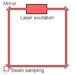
A ring laser gyroscope (RLG) consists of a ring laser having two independent counter-propagating resonant modes over the same path; the difference in the frequencies is used to detect rotation. It operates on the principle of the Sagnac effect which shifts the nulls of the internal standing wave pattern in response to angular rotation. Interference between the counter-propagating beams, observed externally, results in motion of the standing wave pattern, and thus indicates rotation.
Description
The first experimental ring laser gyroscope was demonstrated in the US by Macek and Davis in 1963.[1] Various organizations worldwide subsequently developed ring-laser technology further. Many tens of thousands of RLGs are operating in inertial navigation systems and have established high accuracy, with better than 0.01°/hour bias uncertainty, and mean time between failures in excess of 60,000 hours.
Ring laser gyroscopes can be used as the stable elements (for one degree of freedom each) in an inertial reference system. The advantage of using an RLG is that there are no moving parts (apart from the dither motor assembly, see further description below and laser-lock), compared to the conventional spinning gyroscope. This means there is no friction, which in turn means there will be no inherent drift terms. Additionally, the entire unit is compact, lightweight and virtually indestructible, making it suitable for use in aircraft. Unlike a mechanical gyroscope, the device does not resist changes to its orientation.
Contemporary applications of the Ring Laser Gyroscope (RLG) include an embedded GPS capability to further enhance accuracy of RLG Inertial Navigation Systems (INS)s on military aircraft, commercial airliners, ships and spacecraft. These hybrid INS/GPS units have replaced their mechanical counterparts in most applications. Where ultra accuracy is needed however, spin gyro based INSs are still in use today.[2]
Principle of operation
A certain rate of rotation induces a small difference between the time it takes light to traverse the ring in the two directions according to the Sagnac effect. This introduces a tiny separation between the frequencies of the counter-propagating beams, a motion of the standing wave pattern within the ring, and thus a beat pattern when those two beams are interfered outside the ring. Therefore, the net shift of that interference pattern follows the rotation of the unit in the plane of the ring.
RLGs, while more accurate than mechanical gyroscopes, suffer from an effect known as "lock-in" at very slow rotation rates. When the ring laser is hardly rotating, the frequencies of the counter-propagating laser modes become almost identical. In this case, crosstalk between the counter-propagating beams can allow for injection locking so that the standing wave "gets stuck" in a preferred phase, thus locking the frequency of each beam to each other rather than responding to gradual rotation.
Forced dithering can largely overcome this problem. The ring laser cavity is rotated clockwise and anti-clockwise about its axis using a mechanical spring driven at its resonance frequency. This ensures that the angular velocity of the system is usually far from the lock-in threshold. Typical rates are 400 Hz, with a peak dither velocity of 1 arc-second per second. Dither does not fix the lock-in problem completely, as each time the direction of rotation is reversed, a short time interval exists in which the rotation rate is near zero and lock-in can briefly occur. If a pure frequency oscillation is maintained, these small lock-in intervals can accumulate. This was remedied by introducing noise to the 400 Hz vibration.[3]
Fibre optic gyroscope
A related device is the fibre optic gyroscope which also operates on the basis of the Sagnac effect, but in which the ring is not a part of the laser. Rather, an external laser injects counter-propagating beams into an optical fiber ring, and rotation of the system then causes a relative phase shift between those beams when interfered after their pass through the fiber ring proportional to the rate of rotation. This is therefore less sensitive than the RLG in which the externally observed phase shift is proportional to the accumulated rotation itself, not its derivative. However the sensitivity of the fiber gyro is enhanced by having a long optical fiber coiled for compactness, but in which the Sagnac effect is multiplied according to the number of turns.
Example applications
- Airbus A320[4]
- Agni III[5] and Agni-IV[6]
- Agni-V[7]
- ASM-135 US Anti-satellite missile
- Boeing 757-200
- Boeing 777[8]
- B-52H with the AMI upgrade[9]
- EF-111 Raven
- F-15E Strike Eagle
- F-16 Fighting Falcon
- HAL Tejas
- MC-130E Combat Talon I and MC-130H Combat Talon II
- MQ-1C Warrior
- MK39 Ship's Internal Navigation System used in NATO surface ships and submarines[10]
- P3 Orion (with upgrade)
- Shaurya missile.[11]
- MH-60R, MH-60S, SH60F and SH60B Seahawk helicopters
- Sukhoi Su-30MKI
- Trident I and Trident II Missiles
- PARALIGN, used for roller alignment
- International Space Station
See also
| Wikimedia Commons has media related to Ring laser gyroscopes. |
- Accelerometer
- Active laser medium
- Hemispherical resonator gyroscope
- Laser construction
- Laser science
- List of laser applications
- List of laser types
- Optical ring resonators
References
- ↑ Warren M. Macek and D. T. M. Davis, Jr. (1963) "Rotation rate sensing with traveling-wave ring lasers," Applied Physics Letters, vol. 2, pages 67–68.
- ↑ Peter M. Taylor - INS Test Engineer Honeywell, Inc.
- ↑ Knowing Machines, Donald MacKenzie, The MIT Press, (1991).
- ↑ "Honeywell's ADIRU selected by Airbus". Farnborough: Aviation International News via archive.org. 22–28 July 2002. Archived from the original on 2006-10-17. Retrieved 2008-07-16.
- ↑ "Agni-III missile ready for induction". Press Trust of India. 2008-05-07. Retrieved 2008-05-08.
- ↑ "India successfully test fires Agni-IV missile". Ecconomic Times India via Press Trust of India. 2014-01-20. Retrieved 2015-10-14.
- ↑ "Agni-V missile to take India into elite nuclear club". BBC News. 2012-04-19. Retrieved 2015-10-14.
- ↑ Digital Avionics Systems. IEEE, AIAA. 1995. ISBN 0-7803-3050-1. Retrieved 2008-10-16.
- ↑ "B-52 Maps Its Way Into New Century". fas.org. 19 Nov 1999. Retrieved 2009-02-24.
- ↑ "MK 39 MOD 3A Ring Laser" (PDF).
- ↑ Missile success - Frontline Magazine
External links
- Canterbury Ring Laser Research Group
- Weapons and Systems Engineering Department, United States Naval Academy
- A.D. King (1998). "Inertial Navigation – Forty Years of Evolution" (PDF). GEC Review. General Electric Company plc. 13 (3): 140–149.