Retroreflector
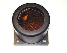 A gold corner cube retroreflector | |
| Uses |
Distance measurement by optical delay line |
|---|---|
A retroreflector (sometimes called a retroflector or cataphote) is a device or surface that reflects light back to its source with a minimum of scattering. In a retroreflector an electromagnetic wavefront is reflected back along a vector that is parallel to but opposite in direction from the wave's source. The angle of incidence at which the device or surface reflects light in this way is greater than zero, unlike a planar mirror, which does this only if the mirror is exactly perpendicular to the wave front, having a zero angle of incidence.
Types
There are several ways to obtain retroreflection:[1]
Corner reflector

A set of three mutually perpendicular reflective surfaces, placed to form the corner of a cube, work as a retroreflector. The three corresponding normal vectors of the corner's sides form a basis (x, y, z) in which to represent the direction of an arbitrary incoming ray, [a, b, c]. When the ray reflects from the first side, say x, the ray's x component, a, is reversed to -a while the y and z components are unchanged. Therefore, as the ray reflects first from side x then side y and finally from side z the ray direction goes from [a,b,c] to [-a,b,c] to [-a,-b,c] to [-a,-b,-c] and it leaves the corner with all three components of motions exactly reversed.
Corner reflectors occur in two varieties. In the more common form, the corner is literally the truncated corner of a cube of transparent material such as conventional optical glass. In this structure, the reflection is achieved either by total internal reflection or silvering of the outer cube surfaces. The second form uses mutually perpendicular flat mirrors bracketing an air space. These two types have similar optical properties.
A large relatively thin retroreflector can be formed by combining many small corner reflectors, using the standard triangular tiling.
Cat's eye

Another common type of retroreflector consists of refracting optical elements with a reflective surface, arranged so that the focal surface of the refractive element coincides with the reflective surface, typically a transparent sphere and (optionally) a spherical mirror. In the paraxial approximation, this effect can be achieved with lowest divergence with a single transparent sphere when the refractive index of the material is exactly one plus the refractive index ni of the medium from which the radiation is incident (ni is around 1 for air). In that case, the sphere surface behaves as a concave spherical mirror with the required curvature for retroreflection. In practice, the optimal index of refraction may be lower than ni+1≅2 due to several factors. For one, it is sometimes preferable to have an imperfect, slightly divergent retroreflection, as in the case of road signs, where the illumination and observation angles are different. Due to spherical aberration, there also exists a radius from the centerline at which incident rays are focused at the center of the rear surface of the sphere. Finally, high index materials have higher Fresnel reflection coefficients, so the efficiency of coupling of the light from the ambient into the sphere decreases as the index becomes higher. Commercial retroreflective beads thus vary in index from around 1.5 (common forms of glass) up to around 1.9 (commonly barium titanate glass).
The spherical aberration problem with the spherical cat's eye can be solved in various ways, one being a spherically symmetrical index gradient within the sphere, such as in the Luneburg lens design. Practically, this can be approximated by a concentric sphere system.[2]
Because the back-side reflection for an uncoated sphere is imperfect, it is fairly common to add a metallic coating to the back half of retroreflective spheres to increase the reflectance, but this implies that the retroreflection only works when the sphere is oriented in a particular direction.
An alternative form of the cat's eye retroreflector uses a normal lens focused onto a curved mirror rather than a transparent sphere, though this type is much more limited in the range of incident angles over which it retroreflects.
The term cat's eye derives from the resemblance of the cat's eye retroreflector to the optical system that produces the well-known phenomenon of "glowing eyes" or eyeshine in cats and other vertebrates (which are only reflecting light, rather than actually glowing). The combination of the eye's lens and the cornea form the refractive converging system, while the tapetum lucidum behind the retina forms the spherical concave mirror. Because the function of the eye is to form an image on the retina, an eye focused on a distant object has a focal surface that approximately follows the reflective tapetum lucidum structure, which is the condition required to form a good retroreflection.
This type of retroreflector can consist of many small versions of these structures incorporated in a thin sheet or in paint. In the case of paint containing glass beads, the paint adheres the beads to the surface where retroreflection is required and the beads protrude, their diameter being about twice the thickness of the paint.
Phase-conjugate mirror
A third, much less common way of producing a retroreflector is to use the nonlinear optical phenomenon of phase conjugation. This technique is used in advanced optical systems such as high-power lasers and optical transmission lines. Phase-conjugate mirrors require a comparatively expensive and complex apparatus, as well as large quantities of power (as nonlinear optical processes can be efficient only at high enough intensities). However, phase-conjugate mirrors have an inherently much greater accuracy in the direction of the retroreflection, which in passive elements is limited by the mechanical accuracy of the construction.
Operation

Retroreflectors are devices that operate by returning light back to the light source along the same light direction. The coefficient of luminous intensity, RI, is the measure of a reflector performance, which is defined as the ratio of the strength of the reflected light (luminous intensity) to the amount of light that falls on the reflector (normal illuminance). A reflector will appear brighter as its RI value increases.[1]
The RI value of the reflector is a function of the color, size, and condition of the reflector. Clear or white reflectors are the most efficient, and appear brighter than other colors. The surface area of the reflector is proportional to the RI value which increases as the reflective surface increases.[1]
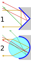
The RI value is also a function of the spatial geometry between the observer, light source, and reflector. Figures 1 and 2 show the observation angle and entrance angle between the automobile's headlights, bicycle, and driver. The observation angle is the angle formed by the light beam and the driver's line of sight. Observation angle is a function of the distance between the headlights and the driver's eye, and the distance to the reflector. Traffic engineers use an observation angle of 0.2 degrees to simulate a reflector target about 800 feet in front of a passenger automobile. As the observation angle increases, the reflector performance decreases. For example, a truck has a large separation between the headlight and the driver's eye compared to a passenger vehicle. A bicycle reflector appears brighter to the passenger car driver than to the truck driver at the same distance from the vehicle to the reflector.[1]
The light beam and the normal axis of the reflector as shown in Figure 2 form the entrance angle. The entrance angle is a function of the orientation of the reflector to the light source. For example, the entrance angle between an automobile approaching a bicycle at an intersection 90 degrees apart is larger than the entrance angle for a bicycle directly in front of an automobile on a straight road. The reflector appears brightest to the observer when it is directly in line with the light source.[1]
The brightness of a reflector is also a function of the distance between the light source and the reflector. At a given observation angle, as the distance between the light source and the reflector decreases, the light that falls on the reflector increases. This increases the amount of light returned to the observer and the reflector appears brighter.[1]
Applications
On roads


Retroreflection (sometimes called retroflection) is used on road surfaces, road signs, vehicles, and clothing (large parts of the surface of special safety clothing, less on regular coats). When the headlights of a car illuminate a retroreflective surface, the reflected light is directed towards the car and its driver (rather than in all directions as with diffuse reflection). However, a pedestrian can see retroreflective surfaces in the dark only if there is a light source directly between them and the reflector (e.g., via a flashlight they carry) or directly behind them (e.g., via a car approaching from behind). "Cat's eyes" are a particular type of retroreflector embedded in the road surface and are used mostly in the UK and parts of the United States.
Corner reflectors are better at sending the light back to the source over long distances, while spheres are better at sending the light to a receiver somewhat off-axis from the source, as when the light from headlights is reflected into the driver's eyes.
Retroreflectors can be embedded in the road (level with the road surface), or they can be raised above the road surface. Raised reflectors are visible for very long distances (typically 0.5–1 kilometer or more), while sunken reflectors are visible only at very close ranges due to the higher angle required to properly reflect the light. Raised reflectors are generally not used in areas that regularly experience snow during winter, as passing snowplows can tear them off the roadways. Stress on roadways caused by cars running over embedded objects also contributes to accelerated wear and pothole formation.
Retroreflective road paint is thus very popular in Canada and parts of the United States, as it is not affected by the passage of snowplows and does not affect the interior of the roadway. Where weather permits, embedded or raised retroreflectors are preferred as they last much longer than road paint, which is weathered by the elements, can be obscured by sediment or rain, and is ground away by the passage of vehicles.
For road signs
Reflectivity is light reflected from a source to a surface and returned to its original source. For traffic signs and vehicle operators, the light source is a vehicle’s headlights, where the light is sent to the traffic sign face and then returned to the vehicle operator. Traffic signs are manufactured with retroreflective sheeting so that the traffic sign is visible at night. Reflective sign faces are manufactured with glass beads or prismatic reflectors imbedded in the sheeting so that the face reflects light, therefore making the sign appear more bright and visible to the vehicle operator. According to the National Highway Traffic Safety Administration (NHTSA), the Traffic Safety Facts 2000 publication states the fatal crash rate is 3-4 times more likely during nighttime crashes than daytime incidents.
A misconception many people have is that retroreflectivity is only important during night-time travel. However, in recent years, more states and agencies are requiring headlights to be used during inclement weather, such as rain and snow. According to the Federal Highway Administration (FHWA): Approximately 24% of all vehicle accidents occur during adverse weather (rain, sleet, snow and fog). Rain conditions account for 47% of weather-related accidents. These statistics are based on 14-year averages from 1995 to 2008.
The Manual on Uniform Traffic Control Devices requires signs to be either illuminated or made with retroreflective sheeting materials and although most signs in the U.S. are made with retroreflective sheeting materials, they degrade over time resulting in a shorter life span. Until now, there has been little information available to determine how long the retroreflectivity lasts. The MUTCD now requires that agencies maintain traffic signs to a set of minimum levels but provide a variety of maintenance methods that agencies can use for compliance. The minimum retroreflectivity requirements do not imply that an agency must measure every sign. Rather, the new MUTCD language describes methods that agencies can use to maintain traffic sign retroreflectivity at or above the minimum levels.
On the Moon

Astronauts on the Apollo 11, 14, and 15 missions left retroreflectors on the Moon as part of the Lunar Laser Ranging Experiment. The Soviet Lunokhod 1 and Lunokhod 2 rovers also carried smaller arrays. Reflected signals were initially received from Lunokhod 1, but no return signals were detected from 1971 until 2010, at least in part due to some uncertainty in its location on the Moon. In 2010, it was found in Lunar Reconnaissance Orbiter photographs and the retroreflectors have been used again. Lunokhod 2's array continues to return signals to Earth.[3] Even under good viewing conditions, only a single reflected photon is received every few seconds. This makes the job of filtering laser-generated photons from naturally-occurring photons challenging.[4]
In satellites
Many artificial satellites carry retroreflectors to be tracked from ground stations. Some satellites were built solely for laser ranging. Other satellites include retroreflectors for orbit calibration, such as in satellite navigation (e.g., most GLONASS satellites and a few GPS satellites) as well as in satellite altimetry (e.g., TOPEX/Poseidon). Retroreflectors can also be used for inter-satellite laser ranging (e.g., GRACE-FO).[5]
Laser ranging satellites
LAGEOS, or Laser Geodynamics Satellites, are a series of scientific research satellites designed to provide an orbiting laser ranging benchmark for geodynamical studies of the Earth. There are two LAGEOS spacecraft: LAGEOS-1 (launched in 1976), and LAGEOS-2 (launched in 1992). They use cube-corner retroreflectors made of fused silica glass. As of 2004, both LAGEOS spacecraft are still in service. Three STARSHINE satellites equipped with retroreflectors were launched beginning in 1999. The LARES satellite was launched on February 13, 2012. (See also List of passive satellites)
BLITS
The BLITS (Ball Lens In The Space) spherical retroreflector satellite was placed into orbit as part of a September 2009 Soyuz launch[6] by the Federal Space Agency of Russia with the assistance of the International Laser Ranging Service, an independent body originally organized by the International Association of Geodesy, the International Astronomical Union, and international committees.[7] The ILRS central bureau is located at the United States' Goddard Space Flight Center.
The reflector, a type of Luneburg lens, was developed and manufactured by the Institute for Precision Instrument Engineering (IPIE) in Moscow.
The purpose of the mission was to validate the spherical glass retroreflector satellite concept and obtain SLR (Satellite Laser Ranging) data for solution of scientific problems in geophysics, geodynamics, and relativity. The BLITS allows millimeter and submillimeter accuracy SLR measurements, as its "target error" (uncertainty of reflection center relative to its center of mass) is less than 0.1 mm. An additional advantage is that the Earth’s magnetic field does not affect the satellite orbit and spin parameters, unlike retroreflectors incorporated into active satellites. The BLITS allows the most accurate measurements of any SLR satellites, with the same accuracy level as a ground target.[8]
The actual satellite is a solid sphere around 17 cm in diameter, weighing 7.63 kg. It is made with two hemispherical shells (outer radius 85.16 mm) of low refractive index glass (n=1.47), and an inner sphere or ball lens (radius 53.52 mm) made of a high refractive index glass (n=1.76). The hemispheres are glued over the ball lens with all spherical surfaces concentric; the external surface of one hemisphere is coated with aluminum and protected by a varnish layer. It was designed for ranging with a green (532 nm) laser. When used for ranging, the phase center is 85.16 mm behind the sphere center, with a range correction of +196.94 mm taking into account the indices of refraction.[9] A smaller spherical retroreflector of the same type but 6 cm in diameter was fastened to the Meteor-3M spacecraft and tested during its space flight of 2001–2006.
Before a collision with space debris, the satellite was in a sun-synchronous circular orbit, 832 km high, with an inclination of 98.77 degrees, an orbital period of 101.3 min, and its own spin period of 5.6 seconds.[9] In early 2013, the satellite was found to have a new orbit 120 m lower, a faster spin period of 2.1 seconds, and a different spin axis.[10] The change was traced back to an event that occurred 22 Jan 2013 at 07:57 UTC; data from the United States’s Space Surveillance Network showed that within 10 seconds of that time BLITS was close to the predicted path of a fragment of the former Chinese Fengyun-1C satellite, with a relative velocity of 9.6 km/s between them. The Chinese government destroyed the Fengyun-1C, at an altitude of 865 km, on 11 Jan 2007 as a test of an anti-satellite missile which resulted in 2,300 to 15,000 debris pieces.
Communications
Modulated retroreflectors, in which the reflectance is changed over time by some means, are the subject of research and development for free-space optical communications networks. The basic concept of such systems is that a low-power remote system, such as a sensor mote, can receive an optical signal from a base station and reflect the modulated signal back to the base station. Since the base station supplies the optical power, this allows the remote system to communicate without excessive power consumption. Modulated retroreflectors also exist in the form of modulated phase-conjugate mirrors (PCMs). In the latter case, a "time-reversed" wave is generated by the PCM with temporal encoding of the phase-conjugate wave (see, e.g., SciAm, Oct. 1990, "The Photorefractive Effect," David M. Pepper, et al.).
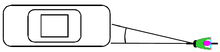
Inexpensive corner-aiming retroreflectors are used in user-controlled technology as optical datalink devices. Aiming is done at night, and the necessary retroreflector area depends on aiming distance and ambient lighting from street lamps. The optical receiver itself behaves as a weak retroreflector because it contains a large, precisely focused lens that detects illuminated objects in its focal plane. This allows aiming without a retroreflector for short ranges.
In fish
A single biological instance of this is known: in flashlight fish of the family Anomalopidae (see Tapetum lucidum).
Ships, boats, emergency gear
Retroflective tape is recognized and recommended by the International Convention for the Safety of Life at Sea (SOLAS) because of its high reflectivity of both light and radar signals. Application to life rafts, personal flotation devices, and other safety gear makes it easy to locate people and objects in the water at night. When applied to boat surfaces it creates a much larger radar signature, particularly for fiberglass boats which produce very little radar reflection on their own. It conforms to International Maritime Organization regulation, IMO Res. A.658 (16) and meets U.S. Coast Guard specification 46 CFR Part 164, Subpart 164.018/5/0. Examples of commercially available products are 3M part numbers 3150A and 6750I.
Other uses
Retroreflectors are used in the following example applications:
- In surveying with a total station or robot, the instrument man or robot aims a laser beam at a corner cube retroreflector held by the rodman. The instrument measures the propagation time of the light and converts it to a distance.
- In Canada, aerodrome lighting can be replaced by appropriately coloured retroreflectors, the most important of which are the white retroreflectors that delineate the runway edges, and must be seen by aircraft equipped with landing lights up to 2 nautical miles away.[11]
- In common (non-SLR) digital cameras, the sensor system is often retroreflective. Researchers have used this property to demonstrate a system to prevent unauthorized photographs by detecting digital cameras and beaming a highly focused beam of light into the lens.[12]
- In movie screens to allow for high brilliance under dark conditions.[13]
- Digital compositing programs and chroma key environments use retroreflection to replace traditional lit backdrops in composite work as they provide a more solid colour without requiring the backdrop to be lit separately.[14]
- In Longpath-DOAS systems retroreflectors are used to reflect the light emitted from a lightsource back into a telescope. It is then spectrally analyzed to obtain information about the trace gas content of the air between the telescope and the retro reflector.
- Barcode labels can be printed on retroreflective material to increase the range of scanning up to 50 feet.[15]
See also
- Corner reflector
- Free-space optical communication
- GPS Block III satellite improvements
- Heiligenschein
- High-visibility clothing
- Optical square
- Modulating retro-reflector
- Reflective prisms
- Retroreflective sheeting and tape
- Safety reflector
Notes
- 1 2 3 4 5 6 U.S. Consumer Product Safety Commission Bicycle Reflector Project report
- ↑ Bernacki, Bruce E.; Anheier, Norman C.; Krishnaswami, Kannan; Cannon, Bret D.; Binkley, K. Brent (2008). "Design and fabrication of effi cient miniature retroreflectors for the mid-infrared". SPIE Defense & Security Conference 2008, Infrared Technology and Applications. Proc. SPIE 6940. XXXIV (30).
- ↑ http://ilrs.gsfc.nasa.gov/docs/williams_lw13.pdf
- ↑ "NASA - Accuracy of Eclipse Predictions". eclipse.gsfc.nasa.gov. Retrieved 2015-08-15.
- ↑
- ↑ "Space Exploration in 2009".
- ↑ "ILRS Missions: BLITS".
- ↑ "BLITS: spin parameters and its optical response measured by the Graz 2kHz SLR system" (PDF).
- 1 2 "BLITS LRS Mission Support Status".
- ↑ "Russian BLITS Satellite hit by Space Debris".
- ↑ Transport Canada CARs 301.07
- ↑ ABC News: Device Seeks to Jam Covert Digital Photographers
- ↑ Howstuffworks "Altered Reality"
- ↑ Thomas, Graham. "Making things Vanish- The Truematte Technology". BBC. Retrieved 25 October 2014.
- ↑ "Retroreflective Labels". MidcomData. Retrieved 2014-07-16.
References
- Optics Letters, Vol. 4, pp. 190–192 (1979), "Retroreflective Arrays as Approximate Phase Conjugators," by H.H. Barrett and S.F. Jacobs.
- Optical Engineering, Vol. 21, pp. 281–283 (March/April 1982), "Experiments with Retrodirective Arrays," by Stephen F. Jacobs.
- Scientific American, December 1985, "Phase Conjugation," by Vladimir Shkunov and Boris Zel'dovich.
- Scientific American, January 1986, "Applications of Optical Phase Conjugation," by David M. Pepper.
- Scientific American, April 1986, "The Amateur Scientist" ('Wonders with the Retroreflector'), by Jearl Walker.
- Scientific American, October 1990, "The Photorefractive Effect," by David M. Pepper, Jack Feinberg, and Nicolai V. Kukhtarev.
External links
| Wikimedia Commons has media related to Retroreflectors. |
- Apollo 15 Laser Ranging Retroreflector Experiment
- Manual of Traffic Signs - Retroreflective Sheetings Used for Sign Faces
- Motorcycle retroreflective Sheeting
- Lunar retroflectors
- Howstuffworks article on retroreflector-based invisibility cloaks
- Reflective Traffic Sign Laws
Part of a series of articles on cars | |||||||||||
| Body | |||||||||||
Exterior equipment |
| ||||||||||
| |||||||||||