Radar engineering details
Radar engineering details are technical details pertaining to the components of a radar and their ability to detect the return energy from moving scatterers — determining an object's position or obstruction in the environment.[1][2][3] This includes field of view in terms of solid angle and maximum unambiguous range and velocity, as well as angular, range and velocity resolution. Radar sensors are classified by application, architecture, radar mode, platform, and propagation window.
Applications of radar include Autonomous cruise control system, autonomous landing guidance, radar altimeter, air traffic management, early-warning radar, fire-control radar, forward warning collision sensing, ground penetrating radar, surveillance, and weather forecasting.
Architecture choice
The angle of a target is detected by scanning the field of view with a highly directive beam. This is done electronically, with a phased array antenna, or mechanically by rotating a physical antenna. The emitter and the receiver can be in the same place, as with the monostatic radars, or be separated as in the bistatic radars. Finally, the radar wave emitted can be continuous or pulsed. The choice of the architecture depends on the sensors to be used.
Scanning antenna

An electronically scanned array (ESA), or a phased array, offers advantages over mechanically scanned antennas such as instantaneous beam scanning, the availability of multiple concurrent agile beams, and concurrently operating radar modes. Figures of merit of an ESA are the bandwidth, the effective isotropically radiated power (EIRP) and the GR/T quotient, the field of view. EIRP is the product of the transmit gain, GT, and the transmit power, PT. GR/T is the quotient of the receive gain and the antenna noise temperature. A high EIRP and GR/T are a prerequisite for long-range detection. Design choices are:
- Active versus passive: In an active electronically scanned array (AESA), each antenna is connected to a T/R module featuring solid state power amplification (SSPA). An AESA has distributed power amplification and offers high performance and reliability, but is expensive. In a passive electronically scanned array, the array is connected to a single T/R module featuring vacuum electronics devices (VED). A PESA has centralized power amplification and offers cost savings, but requires low-loss phase shifters
- Aperture: The Antenna aperture of a radar sensor is real or synthetic. Real-beam radar sensors allow for real-time target sensing. Synthetic aperture radar (SAR) allow for an angular resolution beyond real beamwidth by moving the aperture over the target, and adding the echoes coherently.
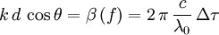
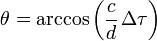
- Architecture: The field of view is scanned with a highly directive frequency-orthogonal (slotted waveguide), spatially orthogonal (switched beamforming networks), or time-orthogonal beams.[4][5][6] In case of time-orthogonal scanning, the beam of an ESA is scanned preferably by applying a progressive time delay,
 , constant over frequency, instead of by applying a progressive phase shift, constant over frequency. Usage of true-time-delay (TTD) phase shifters avoids beam squinting with frequency. The scanning angle,
  , is expressed as a function of the phase shift progression,
  , which is a function of the frequency and the progressive time delay, , which is invariant with frequency:
Note that is not a function of frequency. A constant phase shift over frequency has important applications as well, albeit in wideband pattern synthesis. For example, the generation of wideband monopulse  receive patterns depends on a feed network which combines two subarrays using a wideband hybrid coupler.
- Beam forming: The beam is formed in the digital (digital beamforming (DBF)), intermediate frequency (IF), optical, or radio frequency (RF) domain.
- Construction: An electronically scanned array is a brick, stick, tile, or tray construction. Brick and tray refers to a construction approach in which the RF circuitry is integrated perpendicular to the array plane. Tile, on the other hand, refers to a construction approach in which the RF circuitry is integrated on substrates parallel to the array plane. Stick refers to a construction approach in which the RF circuitry is connected to a line array in the array plane.
- Feed Network: The feed network is constrained (corporate, series) or space-fed.
- Grid: The grid is periodic (rectangular, triangular) or aperiodic (thinned).
- Polarization (antenna): The polarization of ground-based radar sensors is vertical, in order to reduce multipath (Brewster angle). Radar sensors can also be polarimetric for all-weather applications.
FMCW versus pulse-Doppler
The range and velocity of a target are detected through pulse delay ranging and the Doppler effect (pulse-Doppler), or through the frequency modulation (FM) ranging and range differentiation. The range resolution is limited by the instantaneous signal bandwidth of the radar sensor in both pulse-Doppler and FMCW radars. Monostatic monopulse-Doppler radar sensors offer advantages over FMCW radars, such as:
- Half-duplex: Pulse-Doppler radar sensors are half-duplex, while FMCW radar sensors are full-duplex. Hence, pulse-Doppler provide higher isolation between transmitter and receiver, increasing the receiver's dynamic range (DR) and the range detection considerably. In addition, an antenna or an array can be time-shared between transmitter and receiver of the T/R module, whereas FMCW radars require two antennas or arrays, one for transmit and one for receive. A drawback of half-duplex operation is the existence of a blind zone in the immediate vicinity of the radar sensor. Pulse-Doppler radar sensors are therefore more suited for long-range detection, while FMCW radar sensors are more suited for short-range detection.
- Monopulse: A monopulse feed network, as shown in Fig. 2, increases the angular accuracy to a fraction of the beamwidth by comparing echoes, which originate from a single radiated pulse and which are received in two or more concurrent and spatially orthogonal beams.
- Pulse compression: Pulse compression derelates the pulse width and the instantaneous signal bandwidth, which are otherwise inversely related. The pulse width is related to the time-on-target, the signal to noise ratio (SNR) and the maximum range. The instantaneous signal bandwidth is related to the range resolution.
- Pulse-Doppler processing: Echoes originating from a radiated burst are transformed to the spectral domain using a discrete Fourier transform (DFT). In the spectral domain, stationary clutter can be removed because it has a Doppler frequency shift which is different from the Doppler frequency shift of the moving target. The range and velocity of a target can be estimated with increased SNR due to coherent integration of echoes.[7]
Bistatic versus monostatic
Bistatic radars have a spatially dislocated transmitter and receiver. In this case sensor in the transmitting antenna report back to the system the angular position of the scanning beam while the energy detecting ones are with the other antenna. A time synchronisation is crucial in interpreting the data as the receiver antenna is not moving.
Monostatic radars have a spatially co-located transmitter and receiver. It this case, the emission has to be insulated from the reception sensors as the energy emitted is far greater than the returned one.
Platform
Radar clutter is platform-dependent. Examples of platforms are airborne, car-borne, ship-borne, space-borne, and ground-based platforms.
Propagation window
The radar frequency is selected based on size and technology readiness level considerations. The radar frequency is also chosen in order to optimize the radar cross-section (RCS) of the envisioned target, which is frequency-dependent. Examples of progation windows are the 3 GHz (S), 10 GHz (X), 24 GHz (K), 35 GHz (Ka), 77 GHz (W), 94 GHz (W) propagation windows.
Radar Mode
Radar modes for point targets include search and track. Radar modes for distributed targets include ground mapping and imaging. The radar mode sets the radar waveform
See also
- Amplitude monopulse for amplitude-comparison monopulse
- Phase interferometry for phase-comparison monopulse
References
- ↑ G. W. Stimson: "Introduction to Airborne Radar, 2nd Ed.," SciTech Publishing, 1998
- ↑ P. Lacomme, J.-P. Hardange, J.-C. Marchais, E. Normant: "Air and Spaceborne Radar Systems: An Introduction," IEE, 2001
- ↑ M. I. Skolnik: "Introduction to Radar Systems, 3rd Ed.," McGraw-Hill, 2005
- ↑ R. J. Mailloux: "Phased Array Antenna Handbook," Artech House, 2005
- ↑ E. Brookner: "Practical Phased Array Antenna Systems," Artech House, 1991
- ↑ R. C. Hansen: "Phased Array Antennas," John Wiley & Sons, 1998
- ↑ A. Ludloff: "Praxiswissen Radar und Radarsignalverarbeitung, 2. Auflage," Viewegs Fachbücher der Technik, 1998