Pyrometer
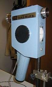
A pyrometer is a type of remote-sensing thermometer used to measure the temperature of a surface. Various forms of pyrometers have historically existed. In the modern usage, it is a device that from a distance determines the temperature of a surface from the spectrum of the thermal radiation it emits, a process known as pyrometry and sometimes radiometry.
The word pyrometer comes from the Greek word for fire, "πυρ" (pyro), and meter, meaning to measure. The word pyrometer was originally coined to denote a device capable of measuring the temperature of an object by its incandescence, visible light emitted by a body which is at least red-hot.[1] Modern pyrometers or infrared thermometers also measure the temperature of cooler objects, down to room temperature, by detecting their infrared radiation flux.
Principle of operation
A modern pyrometer has an optical system and a detector. The optical system focuses the thermal radiation onto the detector. The output signal of the detector (temperature T) is related to the thermal radiation or irradiance j* of the target object through the Stefan–Boltzmann law, the constant of proportionality σ, called the Stefan-Boltzmann constant and the emissivity ε of the object.

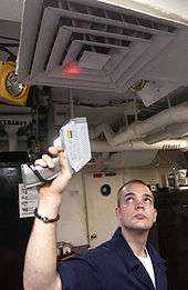
This output is used to infer the object's temperature from a distance, with no need for the pyrometer to be in thermal contact with the object; most other thermometers (e.g. thermocouples and resistance temperature detectors (RTDs)) are placed in thermal contact with the object, and allowed to reach thermal equilibrium.
History
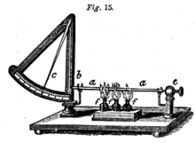
The potter Josiah Wedgwood invented the first pyrometer to measure the temperature in his kilns,[2] which first compared the color of clay fired at known temperatures, but was eventually upgraded to measuring the shrinkage of pieces of clay, which depended on kiln temperature.[3] Later examples used the expansion of a metal bar.[4]
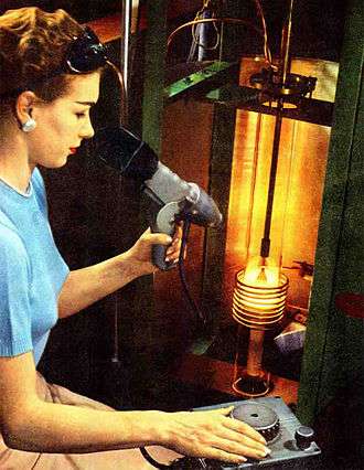
The first disappearing filament pyrometer was built by L. Holborn and F. Kurlbaum in 1901.[5] This device had a thin electrical filament between an observer's eye and an incandescent object. The current through the filament was adjusted until it was of the same colour (and hence temperature) as the object, and no longer visible; it was calibrated to allow temperature to be inferred from the current.[6]
The temperature returned by the vanishing filament pyrometer and others of its kind, called brightness pyrometers, is dependent on the emissivity of the object. With greater use of brightness pyrometers, it became obvious that problems existed with relying on knowledge of the value of emissivity. Emissivity was found to change, often drastically, with surface roughness, bulk and surface composition, and even the temperature itself.[7]
To get around these difficulties, the ratio or two-color pyrometer was developed. They rely on the fact that Planck's law, which relates temperature to the intensity of radiation emitted at individual wavelengths, can be solved for temperature if Planck's statement of the intensities at two different wavelengths is divided. This solution assumes that the emissivity is the same at both wavelengths[6] and cancels out in the division. This is known as the gray body assumption. Ratio pyrometers are essentially two brightness pyrometers in a single instrument. The operational principles of the ratio pyrometers were developed in the 1920s and 1930s, and they were commercially available in 1939.[5]
As the ratio pyrometer came into popular use, it was determined that many materials, of which metals are an example, do not have the same emissivity at two wavelengths.[8] For these materials, the emissivity does not cancel out and the temperature measurement is in error. The amount of error depends on the emissivities and the wavelengths where the measurements are taken.[6] Two-color ratio pyrometers cannot measure whether a material’s emissivity is wavelength dependent.
To more accurately measure the temperature of real objects with unknown or changing emissivities, multiwavelength pyrometers were envisioned at the US National Institute of Standards and Technology and described in 1992.[5] Multiwavelength pyrometers use three or more wavelengths and mathematical manipulation of the results to attempt to achieve accurate temperature measurement even when the emissivity is unknown, changing, and different at all wavelengths.[6][7][8]
Applications
Pyrometers are suited especially to the measurement of moving objects or any surfaces that can not be reached or can not be touched.
Smelter industry
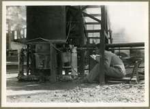
Temperature is a fundamental parameter in metallurgical furnace operations. Reliable and continuous measurement of the melt temperature is essential for effective control of the operation. Smelting rates can be maximized, slag can be produced at the optimum temperature, fuel consumption is minimized and refractory life may also be lengthened. Thermocouples were the traditional devices used for this purpose, but they are unsuitable for continuous measurement because they melt and degrade.
Over-the-bath pyrometer
Salt bath furnaces operate at temperatures up to 1300 °C and are used for heat treatment. At very high working temperatures with intense heat transfer between the molten salt and the steel being treated, precision is maintained by measuring the temperature of the molten salt. Most errors are caused by slag on the surface which is cooler than the salt bath.[9]
Tuyère pyrometer
The tuyère pyrometer is an optical instrument for temperature measurement through the tuyeres which are normally used for feeding air or reactants into the bath of the furnace.
Steam boilers
A steam boiler may be fitted with a pyrometer to measure the steam temperature in the superheater.
Hot air balloons
A hot air balloon is equipped with a pyrometer for measuring the temperature at the top of the envelope in order to prevent overheating of the fabric.
Gas turbine engines
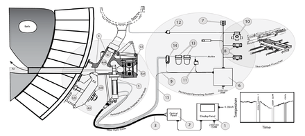
Pyrometers may be fitted to experimental gas turbine engines to measure the surface temperature of turbine blades. Such pyrometers can be paired with a tachometer to tie the pyrometer output with the position of an individual turbine blade. Timing combined with a radial position encoder allows engineers to determine the temperature at exact points on blades moving past the probe.
Pyrometry of gases
Pyrometry of gases presents difficulties. These are most commonly overcome by using thin filament pyrometry or soot pyrometry. Both techniques involve small solids in contact with hot gases.
See also
- Aethrioscope
- Infrared thermometer
- Tasimeter
- Thermal radiation
- Disappearing filament pyrometer
- Thin filament pyrometry
- Thermography
References
- ↑ "incandescence". Dictionary.com. Dictionary.com, LLC. Retrieved 2 January 2015.
- ↑ "History - Historic Figures: Josiah Wedgwood (1730 - 1795)". BBC. 1970-01-01. Retrieved 2013-08-31.
- ↑ "Pyrometer". Wedgwood Museum. Retrieved 23 August 2013.
- ↑ Draper, John William (1861). A Textbook on chemistry. Harper & Bros. p. 24.
- 1 2 3 L. Michalski et al, Temperature Measurement, Second Edition. (Wiley, 2001), pp. 162–208.
- 1 2 3 4 C. Mercer, Optical metrology for fluids, combustion, and solids. (Kluwer Academic, 2003), pp. 297–305.
- 1 2 D. Ng & G. Fralick (2001). "Use of a multiwavelength pyrometer in several elevated temperature aerospace applications". Review Scientific Instruments. 72 (2): 1522. Bibcode:2001RScI...72.1522N. doi:10.1063/1.1340558.
- 1 2 D. Olinger; J. Gray; R. Felice (2007-10-14). Successful Pyrometry in Investment Casting (PDF). Investment Casting Institute 55th Technical Conference and Expo,. Investment Casting Institute. Retrieved 2015-04-02.
- ↑ L. Michalski et al., “Temperature Measurement, Second Edition.(Wiley, 2001), pp. 403-404.
External links
| Wikimedia Commons has media related to Pyrometers. |