Pile driver

A pile driver is a mechanical device used to drive piles (poles) into soil to provide foundation support for buildings or other structures. The term is also used in reference to members of the construction crew that work with pile-driving rigs.
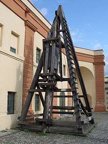
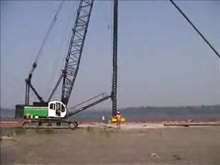
One traditional type of pile driver includes a heavy weight placed between guides so that it is able to freely slide up and down in a single line. It is placed above a pile (pole). The weight is raised, which may involve the use of hydraulics, steam, diesel, or manual labour. When the weight reaches its highest point it is then released and smashes on to the pile in order to drive it into the ground.
History
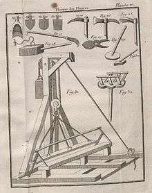
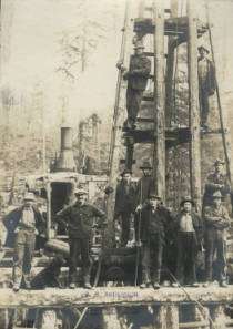
There are a number of claims to the invention of the pile driver. A mechanically sound drawing of a pile driver appeared as early as 1475 in Francesco di Giorgio Martini's treatise Trattato di Architectura.[1] Also, several other prominent inventors — James Nasmyth (son of Alexander Nasmyth), who invented a steam-powered pile driver in 1845,[2] watchmaker James Valoué,[3] Count Giovan Battista Gazzola,[4] and Leonardo da Vinci[5] — have all been credited with inventing the device. However, there is evidence that a comparable device was used in the construction of Crannogs at Oakbank and Loch Tay in Scotland as early as 5000 years ago.[6] In 1801 John Rennie came up with a steam piledriver in Britain.[7] Otis Tufts is credited with inventing the steam pile driver in the United States.[8]

Types
Ancient pile driving equipment used manual or animal labor to lift heavy weights, usually by means of pulleys, to drop the weight onto the end of the pile. Modern piledriving equipment uses various methods to raise the weight and guide the pile.
Diesel hammer
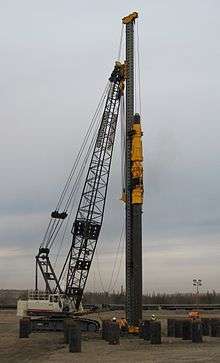
A modern diesel pile hammer is a very large two-stroke diesel engine. The weight is the piston, and the apparatus which connects to the top of the pile is the cylinder. Piledriving is started by having the weight raised by auxiliary means — usually a cable from the crane holding the pile driver — which draws air into the cylinder. Diesel fuel is added/injected into the cylinder. The weight is dropped, using a quick-release. The weight of the piston compresses the air/fuel mixture, heating it to the ignition point of diesel fuel. The mixture ignites, transferring the energy of the falling weight to the pile head, and driving the weight back up. The rising weight draws in fresh air, and the cycle starts over until the fuel runs out or is stopped by the pile crew.
From an army manual on pile driving hammers: The initial start up of the hammer requires the piston (ram) to be raised to a point where the trip automatically releases the piston, allowing it to fall by gravity. As the piston falls, it activates the fuel pump, which discharges a metered amount of fuel into the ball pan of the impact block. The falling piston also blocks the exhaust ports, and compression of fuel trapped in the cylinder begins. The compressed air exerts a pre-load force to hold the impact block firmly against the drive cap and pile. At the bottom of the compression stroke, the piston strikes the impact block, atomizing the fuel and starting the pile on its downward movement. In the instant after the piston strikes, the atomized fuel ignites, and the resulting explosion exerts an even greater force on the already moving pile, driving it further into the ground. The reaction of the explosion rebounding from the resistance of the pile drives the piston upward. As the piston rises, the exhaust ports open, releasing the gases and force of the explosion into the atmosphere. After the piston stops its upward movement, it again falls by gravity to start another cycle.
Vertical Travel Lead Systems
The vertical travel lead, referred to as "VTL" system, was first developed and patented by C.W. Bermingham in the 1970s. This lead system was developed in response to the fundamental limitations of either a fixed lead or swinging lead system. The fixed lead system is well suited to level job sites with few obstructions and has the advantage of faster positioning of the lead. The hanging lead is very adaptable to different elevations and batter piles but takes much longer to position. The Vertical Travel Lead was developed to combine the fast and accurate positioning of fixed leads, with the ability to adjust the height of the lead base up or down. The VTL lead is connected to the boom by a sliding connection, which allows the lead to be elevated or lowered below grade. The VTL system has become the industry standard in Canada, US Railway Construction, and many parts of the USA. Vertical Travel Leads come in two main forms: Spud and Box Lead types. Box leads are very common in the Southern United States and Spud Leads are common in the Northern United States, Canada and Europe.
Hydraulic hammer
A hydraulic hammer is a modern type of piling hammer used in place of diesel and air hammers for driving steel pipe, precast concrete, and timber piles. Hydraulic hammers are more environmentally acceptable than the older, less efficient hammers as they generate less noise and pollutants. However, in many cases the dominant noise is caused by the impact of the hammer on the pile, or the impacts between components of the hammer, so that the resulting noise level can be very similar to diesel hammers.
Hydraulic press-in

Specialty equipment which installs piles using hydraulic rams to press piles into the ground. This system is preferred where vibration is a concern. There are press attachments that can adapt to conventional pile driving rigs to press 2 pairs of sheet piles at a time. Additional types of press equipment sit on top of existing sheet piles and grip onto previously driven piles. This system allows for greater press-in and extraction force to be used since more reaction force is developed. The reaction based machines operate at only 69 dB at 23 ft allowing for installation and extraction of piles in very close proximity to noise and vibration sensitive areas where traditional methods may threaten the stability of existing structures.
Such equipment and methods are specified into portions of the internal drainage system in the New Orleans area after Hurricane Katrina as well as many projects around the world where noise, vibrations and limited access are a concern during the engineering, design and construction phases of the project.
Vibratory pile driver/extractor
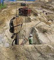
Vibratory pile hammers contain a system of counter-rotating eccentric weights, powered by hydraulic motors, and designed in such a way that horizontal vibrations cancel out, while vertical vibrations are transmitted into the pile. The pile driving machine is lifted and positioned over the pile by means of an excavator or crane, and is fastened to the pile by a clamp and/or bolts. Vibratory hammers can either drive in or extract a pile; extraction is commonly used to recover steel "H" piles used in temporary foundation shoring. Hydraulic fluid is typically supplied to the driver by a diesel engine powered pump mounted in a trailer or van and connected to the driver head through a set of long hoses. When the pile driver is connected to a dragline excavator, it is powered by the excavator's own diesel engine. Vibratory pile drivers are often chosen to mitigate noise, as when the construction is very close to residence or office buildings, or when there is not enough vertical clearance above the foundation to permit use of a conventional pile hammer (for example when retrofitting additional piles to a bridge column or abutment footing). Hammers are available with several different vibration rates, ranging from about 1200 vibrations per minute to about 2400 VPM; the vibration rate chosen is influenced by soil conditions at the site and other factors such as power requirements and purchase price of the equipment.
Piling rig
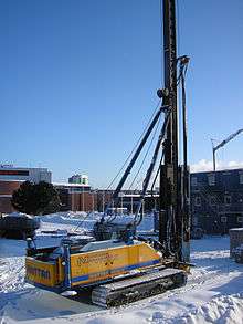
A piling rig is a construction machine for piling in foundation engineering. It is mainly applied to drill in sandy soil, clay, silty clay, etc. and widely used cast-in-place piles, diaphragm walls, foundation reinforcement and other foundation projects. Its rated power of engine is around 108–450 kW, output torque 60–400 kN•m, maximum pile diameter 1.5–4 m, maximum pile depth 60–90 m. It can meet construction requirement of kinds of foundation engineering projects. It generally applies hydraulic crawler chassis, automatic lift box-type mast, telescopic drill pipe, auto vertical adjustor, depth indicator, etc. Its operation applies hydraulic pilot control, load sensor, thus it is easy and comfortable to control. Main and auxiliary hoisting can meet different requirements in construction sites. The rig can be used on piling construction in dry (short screw), wet soil (rotary bucket) and rock (core drill) by equipping with drilling tool, and can be equipped with long screw drill, diaphragm wall grab, vibratory hammer, etc., to realize many functions. It is mainly used in foundation engineering of municipal construction, expressway, bridge, industrial and civil buildings, diaphragm wall, water conservancy project, Slope protection, etc.
Piling rigs categories
- small-sized – torque is around 60–100 kN m, engine power 108 kW, drilling diameter 0.5–1.2 m, drilling depth 40 m, total quality 40 t.
- middle-sized – torque is around 120–180 kN m, engine power 125–200 kW, drilling diameter 0.8–1.8 m, drilling depth 60 m, total quality 42–65 t.
- large-sized - torque is around 240 kN m, engine power 300 kW, drilling diameter 1–2.5 m, drilling depth 80 m, total quality 100 t.
Environmental effects (offshore pile driving)
The underwater sound pressure caused by pile-driving may be deleterious to fish when conducted adjacent to fish-bearing waters.[9][10] State and local regulatory agencies manage environment issues associated with pile-driving.[11]
See also
| Wikimedia Commons has media related to Pile driver. |
References
- ↑ Ladislao Reti, "Francesco di Giorgio Martini's Treatise on Engineering and Its Plagiarists", Technology and Culture, Vol. 4, No. 3. (Summer, 1963), pp. 287–298 (297f.)
- ↑ https://books.google.co.uk/books?id=YWfvDkECNO4C&pg=PA153&lpg=PA153&dq=Nasmyth+Steam+Piledriver&source=bl&ots=VVZDHHaWfw&sig=hl2pZ5Rqm4TZSOb8cEeDXMf6WwA&hl=en&sa=X&ved=0ahUKEwjRzbqy6NrNAhVLlxoKHQCuCzYQ6AEIWjAQ#v=onepage&q=Nasmyth%20Steam%20Piledriver&f=false
- ↑ Science & Society Picture Library Image of Valoué's design
- ↑ Pile-driver Information on Gazzola's design
- ↑ Leonardo da Vinci — Pile Driver Information at Italy's National Museum of Science and Technology
- ↑ History Trails: Ancient Crannogs from BBC's Mysterious Ancestors series
- ↑ https://books.google.co.uk/books?id=TbNwBRrCbn8C&pg=PA3&dq=Steam+Piledriver+Rennie+1801&hl=en&sa=X&ved=0ahUKEwiTrPrYltnQAhUQOsAKHZUsAkYQ6AEIGzAA#v=onepage&q=Steam%20Piledriver%20Rennie%201801&f=false
- ↑ Hevesi, Dennis (July 3, 2008). "R. C. Seamans Jr., NASA Figure, Dies at 89". New York Times. Retrieved 2008-07-03.
His great-great-grandfather Otis Tufts constructed the first steam-operated printing press in the United States and invented the steam pile driver.
- ↑ Halvorsen, M. B., Casper, B. M., Woodley, C. M., Carlson, T. J., & Popper, A. N. (2012). Threshold for onset of injury in Chinook salmon from exposure to impulsive pile driving sounds. Plos One, 7(6), e38968.
- ↑ Halvorsen, M. B., Casper, B. M., Matthews, F., Carlson, T. J., & Popper, A. N. (2012). Effects of exposure to pile-driving sounds on the lake sturgeon, Nile tilapia and hogchoker. Proceedings of the Royal Society of London B: Biological Sciences, 279(1748), 4705-4714.
- ↑ "Fisheries – Bioacoustics". Caltrans. Retrieved 2011-02-03.
External links
- Website about Vulcan Iron Works, which produced pile drivers from the 1870s through the 1990s
- Rock River Thresheree, Inc. has a working American Hoist & Derrick steam pile driver with a Vulcan single-acting steam hammer; it can be seen in action every Labor Day weekend