Photovoltaic thermal hybrid solar collector
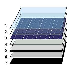
1 - Anti-reflective glass
2 - EVA-encapsulant
3 - Solar PV cells
4 - EVA-encapsulant
5 - Backsheet (PVF)
6 - Heat exchanger (copper)
7 - Insulation (polyurethane)
Photovoltaic thermal hybrid solar collectors, sometimes known as hybrid PV/T systems or PVT, are systems that convert solar radiation into thermal and electrical energy.It is a combination of Photo voltaic and solar thermal systems into a hybrid form known as PVT solar collectors. These systems combine a solar cell, which converts sunlight into electricity, with a solar thermal collector, which captures the remaining energy and removes waste heat from the PV module. The capture of both electricity and heat allow these devices to have higher exergy[1] and thus be more overall energy efficient than solar photovoltaic (PV) or solar thermal alone.[2] A significant amount of research has gone into developing PVT technology since the 1970s.[3]
Various researchers have done various tests on the basis of concentration of incident rays, the collector absorbing plates, glazing materials, tube size, flow rates of fluid used, tank size and it has been found that it has the highest efficiency of operation among the other non-concentrating solar collectors such as flat plate collectors, evacuated tube collectors and having potentially more energy conversion and cost benefits. The parts of a hybrid photo voltaic thermal collector are given below:
- Glass pane
- PV cells
- Piping system
- Insulation
- Adapter
- Frame
Photovoltaic cells suffer from a drop in efficiency with the rise in temperature due to increased resistance. Such systems can be engineered to carry heat away from the PV cells thereby cooling the cells and thus improving their efficiency by lowering resistance.[4] Although this is an effective method, it causes the thermal component to under-perform compared to a solar thermal collector. Recent research showed that photovoltaic materials with low temperature coefficients such as amorphous silicon (a-Si:H) PV allow the PVT to be operated at high temperatures, creating a more symbiotic PVT system.[5][6] This advantage can be tuned by controlling the dispatch strategy of thermal annealing cycles [7] in any region of the world.[8]
System types
A number of PV/T collectors in different categories are commercially available and can be divided into the following categories:
- PV/T liquid collector
- PV/T air collector
- PV/Ta Liquid and air collector
- PV/T concentrator (CPVT)
PV/T liquid collector
The basic water-cooled design uses conductive-metal piping or plates attached to the back of a PV module. The fluid flow arrangement through the cooling element will determine which systems the panels are most suited to.
In a standard fluid based system, a working fluid, typically water, glycol or mineral oil is then piped through these pipes or plate chillers.Here water is generally used as a fluid because of its high heat capacity and excellent optical properties. The heat from the PV cells is conducted through the metal and absorbed by the working fluid (presuming that the working fluid is cooler than the operating temperature of the cells). In closed-loop systems this heat is either exhausted (to cool it), or transferred at a heat exchanger, where it flows to its application. In open-loop systems, this heat is used, or exhausted before the fluid returns to the PV cells.[9] It is also possible to disperse nanoparticles in the liquid to create a liquid filter for PV/T applications.[10][11][12] The basic advantage of this type of split configuration is that the thermal collector and the photovoltaic collector can operate at different temperatures.
PV/T concentrator (CPVT)
A concentrator system has the advantage to reduce the amount of photovoltaic (PV) cells needed, such that somewhat more expensive and efficient multi-junction photovoltaic cells can be used that will maximize the ratio of produced high-value electrical power versus lower-value thermal power. A major limitation of high-concentrator (i.e. HCPV and HCPVT) systems is that they maintain their advantage over conventional c-Si/mc-Si collectors only in regions that remain consistently free of atmospheric aerosol contaminants (e.g. light clouds, smog, etc.). Concentrator system performance is especially degraded because 1) radiation is reflected and scattered outside of the small (often less than 1°-2°) acceptance angle of the collection optics, and 2) absorption of specific components of the solar spectrum causes one or more series junctions within the MJ cells to underperfom.[13]
Concentrator systems also require reliable control systems to accurately track the sun and to protect the PV cells from damaging over-temperature conditions. Under ideal conditions, about 75% of the suns power directly incident upon such systems can be gathered as electricity and heat.
It is a revolutionary new solar technology which can concentrate the sun's radiation 2000 times and convert 80 percent of it to useful energy to generate 12 kw of electrical power and 20 kw of thermal power in a sunny day.It is made up of following main components:
1. Patented fiber based concrete which can be moulded into nearly any shape in less than four hours with mechanical characteristics similar to aluminium at one fifth the cost.
2.The inside of the parabolic dish is covered with 36 elliptic mirrors made of 0.2 mm thin recyclable plastic foil with a silver coating,slightly thicker than the wrapper chocolate bars are packaged in, which are then curved using a slight vacuum.
The mirrored surface area concentrates the sun's radiation by reflection onto several micro-channels liquids cooled receivers each populated with a dense array of multi junction photo voltaic chips - each 1*1 centimeter chip produces an electrical power upto 57 watts when operating over a typical sunny day. Hot water maintains the chip at safe operating temperatures 105 degree. For more details, see the discussion of CPVT within the article for concentrated photovoltaics.
See also
References
- ↑ M.J.M. Pathak, P.G. Sanders, J. M. Pearce, Optimizing limited solar roof access by exergy analysis of solar thermal, photovoltaic, and hybrid photovoltaic thermal systems. In: Applied Energy, 120, pp. 115-124 (2014). doi:10.1016/j.apenergy.2014.01.041
- ↑ Ahmad Mojiri, Robert A. Taylor, Elizabeth Thomsen, Gary Rosengarten, Spectral beam splitting for efficient conversion of solar energy — A review. In: Renewable and Sustainable Energy Reviews 28, December 2013, Pages 654–663, doi:10.1016/j.rser.2013.08.026
- ↑ Chow, T. T. (2010). "A review on photovoltaic/thermal hybrid solar technology". Applied Energy. 87 (2): 365–379. doi:10.1016/j.apenergy.2009.06.037.
- ↑ S.A. Kalogirou, Y. Tripanagnostopoulos (30 January 2006). These systems are most often used for domestic hot water (DHW) and electricity production
- ↑ Pathak, M.J.M.; Pearce, J.M.; Harrison, S.J. (2012). "Effects on amorphous silicon photovoltaic performance from high-temperature annealing pulses in photovoltaic thermal hybrid devices". Solar Energy Materials and Solar Cells. 100: 199–203. arXiv:1203.1216
 . doi:10.1016/j.solmat.2012.01.015.
 - ↑ Pathak, M.J.M; Girotra, K.; Harrison, S.J.; Pearce, J.M. (2012). "The Effect of Hybrid Photovoltaic Thermal Device Operating Conditions on Intrinsic Layer Thickness Optimization of Hydrogenated Amorphous Silicon Solar Cells". Solar Energy. 86: 2673–2677. doi:10.1016/j.solener.2012.06.002.
- ↑ Rozario, J.; Vora, A.H.; Debnath, S.K.; Pathak, M.J.M.; Pearce, J.M. (2014). "The effects of dispatch strategy on electrical performance of amorphous silicon-based solar photovoltaic-thermal systems". Renewable Energy. 68: 459–465. doi:10.1016/j.renene.2014.02.029.
- ↑ Rozario, Joseph; Pearce, Joshua M. (2015). "Optimization of annealing cycles for electric output in outdoor conditions for amorphous silicon photovoltaic–thermal systems". Applied Energy. 148: 134–141. doi:10.1016/j.apenergy.2015.03.073.
- ↑ Y. Tripanagnostopoulos, M. Souliotis, R. Battisti, A. Corrado "APPLICATION ASPECTS OF HYBRID PV/T SOLAR SYSTEMS" http://www.ecn.nl/fileadmin/ecn/units/egon/pvt/pdf/ises03_lca.pdf
- ↑ Taylor, R.A.; Otanicar, T.; Rosengarten, G. (2012). "Nanofluid-based optical filter optimization for PV/T systems". Light: Science & Applications. 1: e34. doi:10.1038/lsa.2012.34.
- ↑ Taylor, R.A.; Otanicar, T; Herukerrupu, Y; Bremond, F; Rosengarten, G; Hawkes, E; Jiang, X.; Coulombe, S (2013). "Feasibility of nanofluid-based optical filters". Applied Optics. 52 (7): 1413–1422. doi:10.1364/AO.52.001413. PMID 23458793.
- ↑ Otanicar, T.P.; Taylor, R. A.; Telang, C. (2013). "Photovoltaic/thermal system performance utilizing thin film and nanoparticle dispersion based optical filters". Journal of Renewable and Sustainable Energy. 5: 033124. doi:10.1063/1.4811095.
- ↑ "Analysis of the spectral variations on the performance of high concentrator photovoltaic modules operating under different real climate conditions, E.F. Fernandez et.al., Solar Energy Materials & Solar Cells, 2014" (PDF).