Parabolic antenna
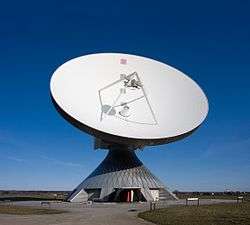
A parabolic antenna is an antenna that uses a parabolic reflector, a curved surface with the cross-sectional shape of a parabola, to direct the radio waves. The most common form is shaped like a dish and is popularly called a dish antenna or parabolic dish. The main advantage of a parabolic antenna is that it has high directivity. It functions similarly to a searchlight or flashlight reflector to direct the radio waves in a narrow beam, or receive radio waves from one particular direction only. Parabolic antennas have some of the highest gains, that is, they can produce the narrowest beamwidths, of any antenna type.[1][2] In order to achieve narrow beamwidths, the parabolic reflector must be much larger than the wavelength of the radio waves used,[2] so parabolic antennas are used in the high frequency part of the radio spectrum, at UHF and microwave (SHF) frequencies, at which the wavelengths are small enough that conveniently-sized reflectors can be used.
Parabolic antennas are used as high-gain antennas for point-to-point communications, in applications such as microwave relay links that carry telephone and television signals between nearby cities, wireless WAN/LAN links for data communications, satellite communications and spacecraft communication antennas. They are also used in radio telescopes.
The other large use of parabolic antennas is for radar antennas, in which there is a need to transmit a narrow beam of radio waves to locate objects like ships, airplanes, and guided missiles.[2] With the advent of home satellite television receivers, parabolic antennas have become a common feature of the landscapes of modern countries.[2]
The parabolic antenna was invented by German physicist Heinrich Hertz during his discovery of radio waves in 1887. He used cylindrical parabolic reflectors with spark-excited dipole antennas at their focus for both transmitting and receiving during his historic experiments.
Design
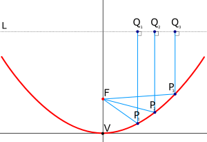
The operating principle of a parabolic antenna is that a point source of radio waves at the focal point in front of a paraboloidal reflector of conductive material will be reflected into a collimated plane wave beam along the axis of the reflector. Conversely, an incoming plane wave parallel to the axis will be focused to a point at the focal point.
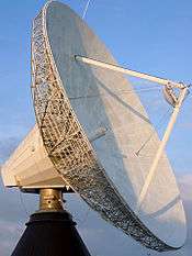
A typical parabolic antenna consists of a metal parabolic reflector with a small feed antenna suspended in front of the reflector at its focus,[2] pointed back toward the reflector. The reflector is a metallic surface formed into a paraboloid of revolution and usually truncated in a circular rim that forms the diameter of the antenna.[2] In a transmitting antenna, radio frequency current from a transmitter is supplied through a transmission line cable to the feed antenna, which converts it into radio waves. The radio waves are emitted back toward the dish by the feed antenna and reflect off the dish into a parallel beam. In a receiving antenna the incoming radio waves bounce off the dish and are focused to a point at the feed antenna, which converts them to electric currents which travel through a transmission line to the radio receiver.
Parabolic reflector
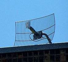
The reflector can be of sheet metal, metal screen, or wire grill construction, and it can be either a circular "dish" or various other shapes to create different beam shapes. A metal screen reflects radio waves as well as a solid metal surface as long as the holes are smaller than one-tenth of a wavelength, so screen reflectors are often used to reduce weight and wind loads on the dish. To achieve the maximum gain, it is necessary that the shape of the dish be accurate within a small fraction of a wavelength, to ensure the waves from different parts of the antenna arrive at the focus in phase. Large dishes often require a supporting truss structure behind them to provide the required stiffness.
A reflector made of a grill of parallel wires or bars oriented in one direction acts as a polarizing filter as well as a reflector. It only reflects linearly polarized radio waves, with the electric field parallel to the grill elements. This type is often used in radar antennas. Combined with a linearly polarized feed horn, it helps filter out noise in the receiver and reduces false returns.
Since a shiny metal parabolic reflector can also focus the sun's rays, and most dishes could concentrate enough solar energy on the feed structure to severely overheat it if they happened to be pointed at the sun, solid reflectors are always given a coat of flat paint.
Feed antenna
The feed antenna at the reflector's focus is typically a low-gain type such as a half-wave dipole or more often a small horn antenna called a feed horn. In more complex designs, such as the Cassegrain and Gregorian, a secondary reflector is used to direct the energy into the parabolic reflector from a feed antenna located away from the primary focal point. The feed antenna is connected to the associated radio-frequency (RF) transmitting or receiving equipment by means of a coaxial cable transmission line or waveguide.
At the microwave frequencies used in many parabolic antennas, waveguide is required to conduct the microwaves between the feed antenna and transmitter or receiver. Because of the high cost of waveguide runs, in many parabolic antennas the RF front end electronics of the receiver is located at the feed antenna, and the received signal is converted to a lower intermediate frequency (IF) so it can be conducted to the receiver through cheaper coaxial cable. This is generally called a low noise amplifier (LNA). Similarly, in transmitting dishes, the microwave transmitter may be located at the feed point.
An advantage of parabolic antennas is that most of the structure of the antenna (all of it except the feed antenna) is nonresonant, so it can function over a wide range of frequencies, that is a wide bandwidth. All that is necessary to change the frequency of operation is to replace the feed antenna with one that works at the new frequency. Some parabolic antennas transmit or receive at multiple frequencies by having several feed antennas mounted at the focal point, close together.


Types
Parabolic antennas are distinguished by their shapes:
- Paraboloidal or dish – The reflector is shaped like a paraboloid truncated in a circular rim. This is the most common type. It radiates a narrow pencil-shaped beam along the axis of the dish.
- Shrouded dish – Sometimes a cylindrical metal shield is attached to the rim of the dish.[3] The shroud shields the antenna from radiation from angles outside the main beam axis, reducing the sidelobes. It is sometimes used to prevent interference in terrestrial microwave links, where several antennas using the same frequency are located close together. The shroud is coated inside with microwave absorbent material. Shrouds can reduce back lobe radiation by 10 dB.[3]
- Cylindrical – The reflector is curved in only one direction and flat in the other. The radio waves come to a focus not at a point but along a line. The feed is sometimes a dipole antenna located along the focal line. Cylindrical parabolic antennas radiate a fan-shaped beam, narrow in the curved dimension, and wide in the uncurved dimension. The curved ends of the reflector are sometimes capped by flat plates, to prevent radiation out the ends, and this is called a pillbox antenna.
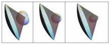
- Shaped-beam antennas – Modern reflector antennas can be designed to produce a beam or beams of a particular shape, rather than just the narrow "pencil" or "fan" beams of the simple dish and cylindrical antennas above.[4] Two techniques are used, often in combination, to control the shape of the beam:
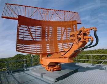
- Shaped reflectors – The parabolic reflector can be given a noncircular shape, and/or different curvatures in the horizontal and vertical directions, to alter the shape of the beam. This is often used in radar antennas. As a general principle, the wider the antenna is in a given transverse direction, the narrower the radiation pattern will be in that direction.
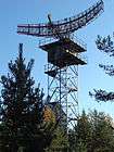
- "Orange peel" antenna – Used in search radars, this is a long narrow antenna shaped like the letter "C". It radiates a narrow vertical fan shaped beam.
- Arrays of feeds – In order to produce an arbitrary shaped beam, instead of one feed horn, an array of feed horns clustered around the focal point can be used. Array-fed antennas are often used on communication satellites, particularly direct broadcast satellites, to create a downlink radiation pattern to cover a particular continent or coverage area. They are often used with secondary reflector antennas such as the Cassegrain.
- Shaped reflectors – The parabolic reflector can be given a noncircular shape, and/or different curvatures in the horizontal and vertical directions, to alter the shape of the beam. This is often used in radar antennas. As a general principle, the wider the antenna is in a given transverse direction, the narrower the radiation pattern will be in that direction.
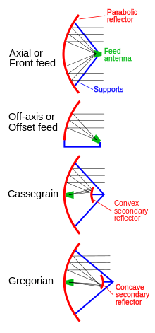
Parabolic antennas are also classified by the type of feed, that is, how the radio waves are supplied to the antenna:[3]
- Axial or front feed – This is the most common type of feed, with the feed antenna located in front of the dish at the focus, on the beam axis, pointed back toward the dish. A disadvantage of this type is that the feed and its supports block some of the beam, which limits the aperture efficiency to only 55–60%.[3]
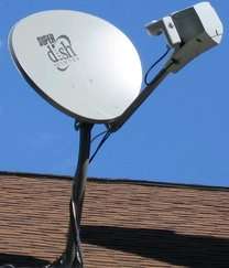
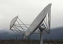
- Off-axis or offset feed – The reflector is an asymmetrical segment of a paraboloid, so the focus, and the feed antenna, are located to one side of the dish. The purpose of this design is to move the feed structure out of the beam path, so it does not block the beam. It is widely used in home satellite television dishes, which are small enough that the feed structure would otherwise block a significant percentage of the signal. Offset feed can also be used in multiple reflector designs such as the Cassegrain and Gregorian, below.
- Cassegrain – In a Cassegrain antenna, the feed is located on or behind the dish, and radiates forward, illuminating a convex hyperboloidal secondary reflector at the focus of the dish. The radio waves from the feed reflect back off the secondary reflector to the dish, which forms the outgoing beam. An advantage of this configuration is that the feed, with its waveguides and "front end" electronics does not have to be suspended in front of the dish, so it is used for antennas with complicated or bulky feeds, such as large satellite communication antennas and radio telescopes. Aperture efficiency is on the order of 65–70%[3]
- Gregorian – Similar to the Cassegrain design except that the secondary reflector is concave, (ellipsoidal) in shape. Aperture efficiency over 70% can be achieved.[3]
Feed pattern
The radiation pattern of the feed antenna has to be tailored to the shape of the dish, because it has a strong influence on the aperture efficiency, which determines the antenna gain (see Gain section below). Radiation from the feed that falls outside the edge of the dish is called "spillover" and is wasted, reducing the gain and increasing the backlobes, possibly causing interference or (in receiving antennas) increasing susceptibility to ground noise. However, maximum gain is only achieved when the dish is uniformly "illuminated" with a constant field strength to its edges. So the ideal radiation pattern of a feed antenna would be a constant field strength throughout the solid angle of the dish, dropping abruptly to zero at the edges. However, practical feed antennas have radiation patterns that drop off gradually at the edges, so the feed antenna is a compromise between acceptably low spillover and adequate illumination. For most front feed horns, optimum illumination is achieved when the power radiated by the feed horn is 10 dB less at the dish edge than its maximum value at the center of the dish.[5]
Dual reflector shaping
In the Cassegrain and Gregorian antennas, the presence of two reflecting surfaces in the signal path offers additional possibilities for improving performance. When the highest performance is required, a technique called "dual reflector shaping" may be used. This involves changing the shape of the sub-reflector to direct more signal power to outer areas of the dish, to map the known pattern of the feed into a uniform illumination of the primary, to maximize the gain. However, this results in a secondary that is no longer precisely hyperbolic (though it is still very close), so the constant phase property is lost. This phase error, however, can be compensated for by slightly tweaking the shape of the primary mirror. The result is a higher gain, or gain/spillover ratio, at the cost of surfaces that are trickier to fabricate and test.[6][7] Other dish illumination patterns can also be synthesized, such as patterns with high taper at the dish edge for ultra-low spillover sidelobes, and patterns with a central "hole" to reduce feed shadowing.
History
The idea of using parabolic reflectors for radio antennas was taken from optics, where the power of a parabolic mirror to focus light into a beam has been known since classical antiquity. The designs of some specific types of parabolic antenna, such as the Cassegrain and Gregorian, come from similarly named analogous types of reflecting telescope, which were invented by astronomers during the 15th century.[8][2]
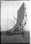
German physicist Heinrich Hertz constructed the world's first parabolic reflector antenna in 1888.[2] The antenna was a cylindrical parabolic reflector made of zinc sheet metal supported by a wooden frame, and had a spark-gap excited dipole as a feed antenna along the focal line. Its aperture was 2 meters high by 1.2 meters wide, with a focal length of 0.12 meters, and was used at an operating frequency of about 450 MHz. With two such antennas, one used for transmitting and the other for receiving, Hertz demonstrated the existence of radio waves which had been predicted by James Clerk Maxwell some 22 years earlier.[9] However, the early development of radio was limited to lower frequencies at which parabolic antennas were unsuitable, and they were not widely used until after World War 2, when microwave frequencies began to be exploited.
Italian radio pioneer Guglielmo Marconi used a parabolic reflector during the 1930s in investigations of UHF transmission from his boat in the Mediterranean.[8] In 1931 a 1.7 GHz microwave relay telephone link across the English Channel using 10 ft. (3 meter) diameter dishes was demonstrated.[8] The first large parabolic antenna, a 9 m dish, was built in 1937 by pioneering radio astronomer Grote Reber in his backyard,[2] and the sky survey he did with it was one of the events that founded the field of radio astronomy.[8]
The development of radar during World War II provided a great impetus to parabolic antenna research, and saw the evolution of shaped-beam antennas, in which the curve of the reflector is different in the vertical and horizontal directions, tailored to produce a beam with a particular shape.[8] After the war very large parabolic dishes were built as radio telescopes. The 100 meter Green Bank Radio Telescope at Green Bank, West Virginia, the first version of which was completed in 1962, is still the world's largest fully steerable parabolic dish.
During the 1960s dish antennas became widely used in terrestrial microwave relay communication networks, which carried telephone calls and television programs across continents.[8] The first parabolic antenna used for satellite communications was constructed in 1962 at Goonhilly in Cornwall, England to communicate with the Telstar satellite. The Cassegrain antenna was developed in Japan in 1963 by NTT, KDDI and Mitsubishi Electric.[10] The advent in the 1970s of computer design tools such as NEC capable of calculating the radiation pattern of parabolic antennas has led to the development of sophisticated asymmetric, multireflector and multifeed designs in recent years.
Gain
The directive qualities of an antenna are measured by a dimensionless parameter called its gain, which is the ratio of the power received by the antenna from a source along its beam axis to the power received by a hypothetical isotropic antenna. The gain of a parabolic antenna is:[12]

where:
- is the area of the antenna aperture, that is, the mouth of the parabolic reflector. For a circular dish antenna, , giving the second formula above.
- is the diameter of the parabolic reflector, if it is circular
- is the wavelength of the radio waves.
- is a dimensionless parameter between 0 and 1 called the aperture efficiency. The aperture efficiency of typical parabolic antennas is 0.55 to 0.70.


It can be seen that, as with any aperture antenna, the larger the aperture is, compared to the wavelength, the higher the gain. The gain increases with the square of the ratio of aperture width to wavelength, so large parabolic antennas, such as those used for spacecraft communication and radio telescopes, can have extremely high gain. Applying the above formula to the 25-meter-diameter antennas often used in radio telescope arrays and satellite ground antennas at a wavelength of 21 cm (1.42 GHz, a common radio astronomy frequency), yields an approximate maximum gain of 140,000 times or about 50 dBi (decibels above the isotropic level).
Aperture efficiency eA is a catchall variable which accounts for various losses that reduce the gain of the antenna from the maximum that could be achieved with the given aperture. The major factors reducing the aperture efficiency in parabolic antennas are:.[13]
- Feed spillover - Some of the radiation from the feed antenna falls outside the edge of the dish and so doesn't contribute to the main beam.
- Feed illumination taper - The maximum gain for any aperture antenna is only achieved when the intensity of the radiated beam is constant across the entire aperture area. However the radiation pattern from the feed antenna usually tapers off toward the outer part of the dish, so the outer parts of the dish are "illuminated" with a lower intensity of radiation. Even if the feed provided constant illumination across the angle subtended by the dish, the outer parts of the dish are farther away from the feed antenna than the inner parts, so the intensity would drop off with distance from the center. So the intensity of the beam radiated by a parabolic antenna is maximum at the center of the dish and falls off with distance from the axis, reducing the efficiency.
- Aperture blockage - In front-fed parabolic dishes where the feed antenna is located in front of the dish in the beam path (and in Cassegrain and Gregorian designs as well), the feed structure and its supports block some of the beam. In small dishes such as home satellite dishes, where the size of the feed structure is comparable with the size of the dish, this can seriously reduce the antenna gain. To prevent this problem these types of antennas often use an offset feed, where the feed antenna is located to one side, outside the beam area. The aperture efficiency for these types of antennas can reach 0.7 to 0.8.
- Shape errors - random surface errors in the shape of the reflector reduce efficiency. The loss is approximated by Ruze's Equation.
For theoretical considerations of mutual interference (at frequencies between 2 and c. 30 GHz - typically in the Fixed Satellite Service) where specific antenna performance has not been defined, a reference antenna based on Recommendation ITU-R S.465 is used to calculate the interference, which will include the likely sidelobes for off-axis effects.
Radiation pattern
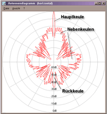
In parabolic antennas, virtually all the power radiated is concentrated in a narrow main lobe along the antenna's axis. The residual power is radiated in sidelobes, usually much smaller, in other directions. Because in parabolic antennas the reflector aperture is much larger than the wavelength, due to diffraction there are usually many narrow sidelobes, so the sidelobe pattern is complex. There is also usually a backlobe, in the opposite direction to the main lobe, due to the spillover radiation from the feed antenna that misses the reflector.
Beamwidth
The angular width of the beam radiated by high-gain antennas is measured by the half-power beam width (HPBW), which is the angular separation between the points on the antenna radiation pattern at which the power drops to one-half (-3 dB) its maximum value. For parabolic antennas, the HPBW θ is given by:[5][14]

where k is a factor which varies slightly depending on the shape of the reflector and the feed illumination pattern. For an ideal uniformly illuminated parabolic reflector and θ in degrees, k would be 57.3 (the number of degrees in a radian). For a "typical" parabolic antenna k is approximately 70.[14]
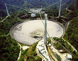
For a typical 2 meter satellite dish operating on C band (4 GHz), this formula gives a beamwidth of about 2.6°. For the Arecibo antenna at 2.4 GHz the beamwidth is 0.028°. It can be seen that parabolic antennas can produce very narrow beams, and aiming them can be a problem. Some parabolic dishes are equipped with a boresight so they can be aimed accurately at the other antenna.
It can be seen there is an inverse relation between gain and beam width. By combining the beamwidth equation with the gain equation, the relation is:[14]

See also
- Cassegrain antenna
- Feed horn
- Offset dish antenna
- Parabolic reflector
- Radio telescope
- Satellite dish
- Simulsat (a quasi parabolic antenna which is spherical in one plane and parabolic in another)
References
- ↑ Straw, R. Dean, Ed. (2000). The ARRL Antenna Book, 19th Ed. USA: American Radio Relay League. p. 19.15. ISBN 0-87259-817-9.
- 1 2 3 4 5 6 7 8 9 Stutzman, Warren L.; Gary A. Thiele (2012). Antenna Theory and Design, 3rd Ed. US: John Wiley & Sons. pp. 391–392. ISBN 0470576642.
- 1 2 3 4 5 6 Lehpamer, Harvey (2010). Microwave transmission networks: Planning, Design, and Deployment. USA: McGraw Hill Professional. pp. 268–272. ISBN 0-07-170122-2.
- ↑ A. David Olver (1994) Microwave Horns and Feeds, p. 61-62
- 1 2 Straw, R. Dean, Ed. (2000). The ARRL Antenna Book, 19th Ed. USA: American Radio Relay League. p. 18.14. ISBN 0-87259-817-9.
- ↑ Galindo, V. (1964). "Design of dual-reflector antennas with arbitrary phase and amplitude distributions". Antennas and Propagation, IEEE Transactions on. IEEE. 12 (4): 403–408. doi:10.1109/TAP.1964.1138236.
- ↑ Willams, WF (1983). "RF Design and Predicted Performance for a Future 34-Meter Shaped Dual-Reflector Antenna System Using the Common Aperture XS Feedhorn" (PDF). Telecommunications and Data Acquisition Progress Report. 73: 74–84.
- 1 2 3 4 5 6 Olver, A. David (1994). Microwave horns and feeds. USA: IET. p. 3. ISBN 0-7803-1115-9.
- ↑ Love, Allan W. "Large Space Antenna Concepts for ESGP" (PDF). Rockwell International. Retrieved 2009-07-31.
- ↑ Makino, Shigero (2006). "Historical review of reflector antenna systems developed for satellite communication by MELCO" (PDF). ISAP2006-International Symposium on Antennas and Propagation. Mitsubishi Electric Corp. Retrieved 2011-12-24. on ISAP website
- ↑ Drentea, Cornell (2010). Modern Communications Receiver Design and Technology. USA: Artech House. p. 369. ISBN 1-59693-309-7.
- ↑ Anderson, Harry R. (2003). Fixed broadband wireless system design. USA: John Wiley & Sons. pp. 206–207. ISBN 0-470-84438-8.
- ↑ Pattan, Bruno (1993). Satellite systems: principles and technologies. USA: Springer. p. 267. ISBN 0-442-01357-4.
- 1 2 3 Minoli, Daniel (2009). Satellite Systems Engineering in an IPv6 Environment. USA: CRC Press. p. 78. ISBN 1-4200-7868-2.
External links
![]() Media related to Parabolic antennas at Wikimedia Commons
Media related to Parabolic antennas at Wikimedia Commons
- WiFi: Parabolic Dish with BiQuad feeder
- Online Satellite Finder Based on Google Maps
- Antenna types: Parabolic Antenna for WiFi
- Online pointing utility using google maps, and each satellite channel list: http://www.dishpointer.com/
- Animation of Propagation from a Parabolic Dish Antenna from YouTube
- Parabolic reflector antenna tutorial Theory and practice
- Applet of gain of parabolic antenna.