
Failed IC in a laptop. Wrong input voltage has caused massive overheating of the chip and melted the plastic casing.
Overheating is a phenomenon of rising of temperature in an electric circuit (or portion of a circuit). Overheating causes potential damage to the circuit components, and can cause fire, explosion, or injury. The parts damages caused by overheating are commonly irreversible; i.e. the only way to repair, is to replace some components.
Causes
On overheating, the temperature of the part rises above the operating temperature. Overheating can take place
- if heat is produced in more than expected amount (such as in cases of short-circuits, or applying more voltage than rated), or
- if heat dissipation (drainage-out of heat) is poor, so that normally-produced waste heat does-not drained away properly.
Overheating may be caused from any accidental-fault-of the circuit (such as short-circuit or spark-gap), or may be caused from a wrong design or manufacture ( uch as lack of proper heat-dissipation system).
Due to accumulation of heat, the system reaches to an equilibrium of heat accumulation vs. dissipation, at a much-higher temperature than expected.
| Gallery: some causes, effects, and cause-effect loops for overheating |
|---|
| A short circuit caused by overvoltage blow up a integrated circuit. |
| Joule-heating or resistive heating sometimes helpful such as in heating coil. But Joule heating occurs in to-some-extent in all the conductive parts of circuit |
| infrared-thermal image of a motor |
| An electric arc created between two nails |
| Electric arc (spark) between two wires. It can cause overheating and ignition (fire). |
| On un-insulated wires, trees facilitated short-circuit in storms. |
| An insulator can handle only certain voltage, above-which, a breakdown of the insulator take place. Voltage-current relation before breakdown. |
| Electricity applied to start up a fire (ignite) wastes in an incinerator. Same could be happen in a circuit or building. |
|
Preventive measures
Use of circuit breaker or fuse
Circuit-breakers placed at different portions of circuit (in series to the path of current it will affect). If more current than expected goes through the circuit-breaker, the circuit breaker "opens" the circuit and stops all current.
A fuse is a kind of widely used circuit breaker, that involves direct effect of Joule-overheating. A fuse is always placed in series with the path of current it will affect. Depending upon work, inside a fuse, there is a narrow (often a hairline) wire of definite-material, in the fuse. When more-than expected current flows through the fuse; the fuse-wire overheats (melts) and "opens" the circuit. In some gadgets, more than one
| Gallery: Circuit breakers and fuses used to stop current. |
|---|
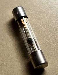
| Miniature time-delay fuse to interrupt 0.3 A current at 250 V after 100 s, and 15 A current at 250 V in 0.1 s |
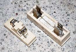
| MEM rewirable fuse holders (30 A and 15 A) |
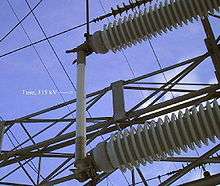
| A 115 kV high-voltage fuse near a hydroelectric power plant |
| A two-pole miniature circuit breaker |
| Inside of a circuit breaker |
|
Use of heat-dissipating systems
Many ventilator holes or slits kept on the box of equipments. Heat sinks (heat-radiating metallic objects) attached with some-portions of the circuit that produce more heat/ more vulnerable to heat. often, fans are required. Some high-voltage instruments kept immersed in oil. In some cases, to remove unwanted heat, some cooling-system like air-condition or refrigerating-heat-pumps may be required.
| Gallery: Methods of improving heat dissipation from equipment |
|---|
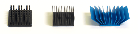
| A pin-, straight- and flared fin heat sink types. |
| pin fin heat sink with thermal profile and air flow movement |
| straight finned heat sink with thermal profile and air flow |
| Active heat sink with a fan and heat pipes. |
| A fan-cooled heat sink on the processor of a personal computer. |
| Passive heatsink on a chipset. |
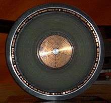
| Oil transformer with air convection cooled heat exchangers |
| Small resistor with low power (watt)-dissipation capacity. Useful only at low voltage. |
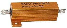
| An aluminium-housed power resistor rated for 50 W when heat-sinked |
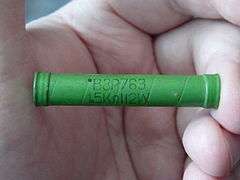
| VZR power resistor 1.5 kΩ 12 W |
|
Control within circuit-design
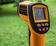
Sometimes special circuits built for purpose of sensing the temperature or voltage status, and thereafter controlling these variables. In these circuits, Thermistors (Temperature dependent resistors), VDR (voltage-dependent resistors), thermostat (that switches off the circuit at higher-temperature), Sensors (such as infrared-thermometers), etc. used to modify the current upon different conditions like circuit-temperature and input voltage.
| Gallery: Control of temperature with special mechanisms in circuits |
|---|
| Bimetallic thermostat for buildings |
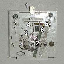
| Millivolt thermostat interior mechanism |
| Bimetallic strip-thermostat working principle schematic |
| working principle of bimetallic strip. |
| Bimetal coil reacts to lighter |
| Thermistors. They can be NTC or PTC according response to warming. |
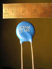
| Metal-oxide varistor (voltage-dependent resistor) |
|
Proper manufacture
For a certain definite purpose in a definite electrical equipment or a portion of it, definite type and size of materials (for boards,wires, insulators) with proper rating for voltage, current and temperature,are used. The circuit-resistance never kept too-low. Sometimes some parts placed inside the board and box, maintaining a proper distance from each-other, to avoid heat-damage and short-circuit-damage. To prevent short-circuit, on the wire-joints, appropriate type of electrical connectors and mechanical fasteners used.
| Gallery: material-requirement for circuit build-up |
|---|
| A device for measuring standard wire gauge. |
| Stranded copper lamp cord, 16 gauge |
| Cross-section of copper high-voltage cable rated at 400 kV. |
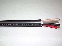
| 3-core copper wire power cable, each core with individual colour-coded insulating sheaths all contained within an outer protective sheath |
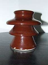
| 10 kV ceramic insulator, showing sheds |
|
See also
References
Sources
- ↑ http://www.ufba.org.nz/images/documents/hazardsandsafeguards.pdf
- ↑ "Classification of Electrical Overheating Modes - Electro-Mechanical Recertifiers, Inc.". Retrieved 27 August 2016.
- ↑ ElectroTechnik. "What are the reasons for transformer overheating?". Retrieved 27 August 2016.
- ↑ "The Basics of Electrical Overheating". Retrieved 27 August 2016.
- ↑ http://www.testequipmentdepot.com/application-notes/pdf/power-quality/case-study-the-overheating-transformer_an.pdf
- ↑ http://protectowire.com/documents/ds-8899.pdf
- ↑ http://www.mirusinternational.com/downloads/hmt_faq10.pdf
- ↑ http://www.learnabout-electronics.org/Downloads/ac_theory_module11.pdf
- ↑ "Power Transformers". Retrieved 27 August 2016.
- ↑ http://sound.westhost.com/xfmr.htm
- ↑ http://sound.westhost.com/xfmr-6.jpg
- ↑ "Top 14 Reasons Electrical Service Installations Get Red Tagged". Retrieved 27 August 2016.
- ↑ http://ecmweb.com/site-files/ecmweb.com/files/uploads/2016/03/Electrical-Service-Meltdown-6.jpg


.png)
