Oudin coil

An Oudin coil, also called an Oudin oscillator or Oudin resonator, is a resonant transformer circuit that generates very high voltage, high frequency alternating current (AC) electricity at low current levels,[1][2][3] used in the obsolete medical field of electrotherapy around the turn of the 20th century.[4] It is very similar to a Tesla coil, with the difference being that the Oudin coil was connected as an autotransformer.[2][5] It was invented in 1893 by French physician Paul Marie Oudin[6] as a modification of physician Jacques Arsene d'Arsonval's electrotherapy equipment[7][8] and used in quack medicine until perhaps 1930. The high voltage output terminal of the coil was connected to an insulated handheld electrode which produced luminous brush discharges, which were applied to the patient's body to treat various medical conditions in electrotherapy.[4]
How it works
Oudin and Tesla coils are spark-excited air-core double-tuned transformer circuits that use resonance to generate very high voltages at low currents.[9][10] They produce alternating current in the radio frequency (RF) range. The medical coils of the early 20th century produced potentials of 50,000 to nearly a million volts, at frequencies in the range 200 kHz to 5 MHz.[4] The primary circuit of the coil has Leyden jar capacitors (C) (one in the Tesla and two in the Oudin coil) which in combination with the primary winding of the coil (L1) make a tuned circuit.[4] The primary circuit also has a spark gap (SG) to excite oscillations in the primary. The primary circuit is powered by a high voltage transformer or induction coil[4] (T) at a potential of 2 - 15 kV. The transformer repeatedly charges the capacitors, which then discharge through the spark gap and the primary winding. This cycle is repeated many times per second. During each spark, the charge moves rapidly back and forth between the capacitor plates through the primary coil, creating a damped RF oscillating current in the primary tuned circuit which induced the high voltage in the secondary.
The secondary winding (L2) is open-circuited, and connected to the output electrode of the device. In the Oudin coil, one side of the primary winding (L1) is grounded and the other side is connected to the secondary, so the primary and secondary are in series. There were two versions of the Oudin coil:[3][11][12]


- In earlier Oudin circuits the two coils were separate, not magnetically coupled, with a small horizontal primary "D'Arsonval" coil of 20-40 turns with a tap connected to a large vertical secondary "Oudin resonator" with many turns of fine wire (400 - 600 in large coils, 100 - 300 in small ones),[2] connected to the high voltage terminal on top. In this circuit the high voltage was generated entirely by resonance in the high Q secondary coil. The addition of the "resonator" coil to the "D'Arsonval" coil was Oudin's contribution; the rest of the circuit was invented by Jacques D'Arsonval.[3]


- In later Oudin circuits the coils were magnetically coupled, forming an autotransformer, so the primary induces an EMF in the secondary by electromagnetic induction. Both coils were usually wound on the same coil form, the primary consisting of relatively few turns of heavy wire at the bottom with an adjustable tap, connected to the secondary winding, made of many turns of fine wire.[3] Oudin found this circuit produced higher voltages due to the large turns ratio of the transformer.
Although it doesn't include a capacitor, the secondary winding is also a tuned circuit (electrical resonator); the parasitic capacitance between the ends of the secondary coil resonates with the large inductance of the secondary at a particular resonant frequency. When it is excited at this frequency by the primary, large oscillating voltages are induced in the secondary. The number of turns in the primary winding, and thus the resonant frequency of the primary, could be adjusted with a tap on the coil. When the two tuned circuits are adjusted to resonate at the same frequency, the large turns ratio of the coil, aided by the high Q of the tuned circuits, steps up the primary voltage to hundreds of thousands to millions of volts at the secondary.
In the Oudin circuit, unlike the Tesla, the secondary is directly connected to the primary circuit, which can carry lethal currents from the power transformer. Since the Oudin coil was a medical device, with the secondary current applied directly to a person's body, for safety the Oudin circuit has two capacitors (C), one in each leg of the primary, to completely isolate the coil and output electrode from the supply transformer at the mains frequency.[13] Because two identical capacitors in series have half the capacitance of a single capacitor, the resonant frequency of the Oudin circuit is


Use


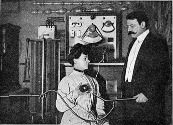
The high voltage terminal of the coil was attached through a wire to various types of handheld electrode which the physician used to apply the high voltage to the patient's body. The treatment was not painful for the patient, because alternating current in the radio frequency (RF) range, above 10 kHz in frequency, does not generally cause the sensation of electric shock. The Oudin coil was a "unipolar" generator, with the lower end of the coil grounded, so sometimes only one electrode was applied to the patient and the return path for the currents was through the ground. However usually a ground wire from the bottom of the coil was used; attached to a ground electrode which the patient held. A drawback of the Oudin coil was that movement of the electrode and wire during use changed the capacitance of the top terminal of the secondary coil, and thus its resonant frequency.[14] This threw the secondary coil out of resonance with the primary, causing a reduction in voltage. So the tap point on the primary coil had to be constantly adjusted during use to keep the primary and secondary in "tune" (seen in left image above).
Many specialized types of electrodes were used to apply the current to various parts of the patient's body. These generally fell into two types. To apply brush discharges (called "effluves") to the outside of the patient's body, electrodes consisting of one or more metal points on an insulating handle were used. Care had to be taken to keep these far enough from the body to prevent an arc to the skin, which could cause painful RF burns. To apply current directly to the body surface, as well as to tissues inside the patient's body through the mouth, rectum, or vagina, a vacuum tube "condensing" electrode was used. This consisted of a partially evacuated glass tube of various shapes, with an electrode sealed inside, attached to the high voltage wire. This produced a dramatic violet glow when energized. The glass envelope of the tube formed a capacitor with the patient's body through which the current had to pass, limiting it to safe values.
To apply current to the whole body, a "condensing couch" was used. This was a bed or couch with a metal back under its mattress, connected by a wire to the high voltage terminal. Metal handrest electrodes at the sides, which the patient grasped during treatment, served as the "ground" return path and were attached to the bottom of the coil. Thus the couch formed a capacitor, with the patient's body as one electrode.
History
During the 1800s, experiments in applying electric currents to the human body grew into a Victorian-era medical field, part legitimate experimental medicine and part quack medicine, called electrotherapy. The discovery of radio waves by Heinrich Hertz in 1886 and subsequent development of radio by Oliver Lodge, Guglielmo Marconi sparked interest in radio frequency currents and circuits for generating them. "High frequency" currents meant any frequency above the audio range, and the resonant coils which generated them were generically called "oscillation transformers". During the 1890s doctors began to experiment with applying these high voltage and high frequency currents to the human body (ethical standards in the medical profession were looser then and physicians could experiment on their patients). Three types of apparatus were used, developed by three pioneers in the field, D'Arsonval, Tesla, and Oudin, and separate bodies of clinical technique grew up around them:[3][4]
.jpg)

- D'Arsonval apparatus - In 1890 French physician Jacques Arsene d'Arsonval founded the field of high frequency electrotherapy, performing the first experiments applying high frequency currents to the human body. He discovered that currents above 10 kHz do not cause muscle contraction or activate nerves to cause the sensation of electric shock. D'Arsonval first used a high frequency alternator, but this device could not produce frequencies over 10 kHz. To reach higher frequencies he developed a circuit consisting of a single tuned circuit, made of two Leyden jar capacitors and a small coil of relatively few, 10 to 30 turns of heavy wire, with an induction coil and spark gap to excite oscillations. It resembled a Tesla circuit without the secondary winding. The circuit produced relatively low voltage (perhaps 30 kV), high current electricity, called "D'Arsonval currents". The circuit was "bipolar" with two wires from opposite ends of the coil connected to electrodes at different places on the patient's body. The high frequency currents could produce heat in the patient's body, similar to the operation of a microwave oven; this was called Diathermy (Behary). Other names were also used such as Thermo-Faradism and Thermo-Penetration depending on whether it was used for therapy or for destructive effects in surgery (Behary)
- Oudin resonator - French physician Paul Marie Oudin in 1893 modified the D'Arsonval circuit by adding a second large "resonator" coil made of many turns of fine wire to a tap on the small D'Arsonval coil. By adjusting the tap point he could bring the second coil to resonance with the tuned circuit, generating higher voltages at lower currents, similar to the Tesla circuit. In early "Oudin resonator" apparatus the two coils are separate and not magnetically coupled. Later Oudin found that the efficiency could be increased by magnetically coupling the coils, making the small coil the primary winding for the big coil.[11] The Oudin resonator generated very high voltage, low current electricity. It was a "unipolar" circuit, with one end grounded and a single output terminal.
- Tesla-Thomson apparatus - Serbian-American engineer Nikola Tesla pioneered the field of high-voltage RF resonant transformers. He and Elihu Thomson experimented with applying the high voltage to his body. Although Tesla invented many different resonant transformer circuits, the electrotherapy circuit that bears his name was a "bipolar" circuit consisting of a spark-excited tuned primary coil of few turns encircling the center of a symmetrical bipolar secondary coil of many turns of fine wire, with output terminals on each end.
The D'Arsonval and Oudin apparatus became popular in Europe, while the Tesla-Thompson apparatus was mostly used in America. During the first decades of the 20th century there was a rivalry between these camps, and debate in the medical literature as to whether "Tesla currents" or "Oudin currents" were better for various conditions. By 1920 it was realized that the currents were very similar. Since the circuits were so similar, medical suppliers sold combination "high frequency" units that could be set up for Tesla, D'Arsonval, or Oudin therapy, often also combined with Rontgen ray (x-ray)
After Oudin combined the primary and "resonator" coil together on the same form, making them an air-core autotransformer, the only significant difference between the Tesla and Oudin apparatus was that the medical Tesla coil was "bipolar" while the Oudin coil was "unipolar", with one end grounded. As time went on the meaning of the terms changed, until (by perhaps 1920) the term Tesla coil meant a "bipolar" coil; any high voltage coil with an ungrounded balanced secondary with two output terminals, while the term Oudin coil meant a "unipolar" coil; any coil with a grounded secondary and a single output terminal.[11]
Around the 1930s vacuum tube oscillators replaced spark-excited circuits in high frequency medical equipment. The field of electrotherapy was replaced by the modern field of diathermy, and the Oudin coil became obsolete. Ironically modern day Tesla coil designs are unipolar, with a single high voltage terminal, and so are sometimes called Oudin coils.[11][15]
See also
References
- ↑ Strong, Frederick Finch (1908). High-frequency currents. Rebman Company. p. 41.
- 1 2 3 Curtis, Thomas Stanley (1916). High Frequency Apparatus: Its Construction and Practical Application. New York: Everyday Mechanics Co. Inc. pp. 45–47.
- 1 2 3 4 5 Martin, James M. (1912). Practical electro-therapeutics and X-ray therapy. C.V. Mosby Co. pp. 187–192.
- 1 2 3 4 5 6 Strong, Frederick Finch (1918). Essentials of modern electro-therapeutics (2 ed.). New York: Rebman Co. pp. 73–75.
- ↑ Hickman, Bert (November 30, 2000). "Re: Oudin vs Tesla coils". Tesla Coil Mailing List. Chip Atkinson's website. Retrieved December 2, 2014. External link in
|work=(help) - ↑ Manders, Horace (August 1, 1902). "Some phenomena of high frequency currents". Journal of Physical Therapeutics. London: John Bale, Sons, and Danielsson, Ltd. 3 (1): 226. Retrieved December 2, 2014.
- ↑ Filingeri, V.; Gravante, G.; Cassisa, D. (2005). "Physics of radiofrequency in proctology" (PDF). European Review for Medical and Pharmacological Sciences. 9 (6): 349. Retrieved April 11, 2015.
- ↑ Eberhart, Noble Murray (1919). A Working Manual of High Frequency Currents (5 ed.). Chicago: New Medicine Publishing Co. p. 40.
- ↑ Brewster, Frank (June 1914). "High Frequency Current Apparatus Ch. 5: High Frequency Transformer". Modern Electrics and Magnetics. New York: Modern Publishing Co. 28 (6): 762–764. Retrieved December 2, 2014.
- ↑ Naidu, M. S.; Kamaraju, V. (2009). High Voltage Engineering. India: Tata McGraw-Hill Education. p. 170. ISBN 0070669287.
- 1 2 3 4 Behary, Jeff (July 1, 2007). "Re: Oudin coil". Tesla list (Mailing list). Retrieved April 10, 2015.
- ↑ Tousey, Sinclair (1921). Medical electricity Rontgen rays and Radium, 3rd Ed. W.B. Saunders Co. pp. 541, 548–550.
- ↑ Manders, 1902, Some phenomena of high frequency currents, p. 220-221
- ↑ Manders, 1902, Some phenomena of high frequency currents, p. 223
- ↑ Skelton, Ken. "Oudin Oscillator". Public Understanding of Science. Dept. of Physics and Astronomy, Univ. of Glasgow. Retrieved April 10, 2015. External link in
|publisher=(help) Archived April 4, 2005, at the Wayback Machine.