Mullard–Philips tube designation
In Europe, the principal method of numbering vacuum tubes ("thermionic valves") was the nomenclature used by the Philips company and its subsidiaries Mullard in the UK, Valvo in Germany, and Dario in France, from 1934. This system allocated meaningful codes to tubes based on their function. This European common code system became the starting point for the Pro Electron naming scheme for active devices (including tubes and transistors).
Nomenclature systems
The system allowed for cross-referencing with the American RETMA tube designation, the Marconi-Osram tube designation, and with military numbering systems such as common valve (CV) numbering in the United Kingdom and the Joint Army–Navy (JAN) tube designation in the US.
European tube manufacturers agreed on the system, but in the UK, MOV (Marconi-Osram Valve), STC/Brimar and Mazda/Ediswan maintained their own systems. Most MOV tubes were cross-licensed copies of RCA types, with a British designation. For example, an MOV X63 valve was the same as an RCA 6A8 tube. Brimar, which stood for "British Manufactured American Radio" (valves), used all American designations. STC/Brimar was a UK subsidiary of the American giant ITT (International Telephone and Telegraph).
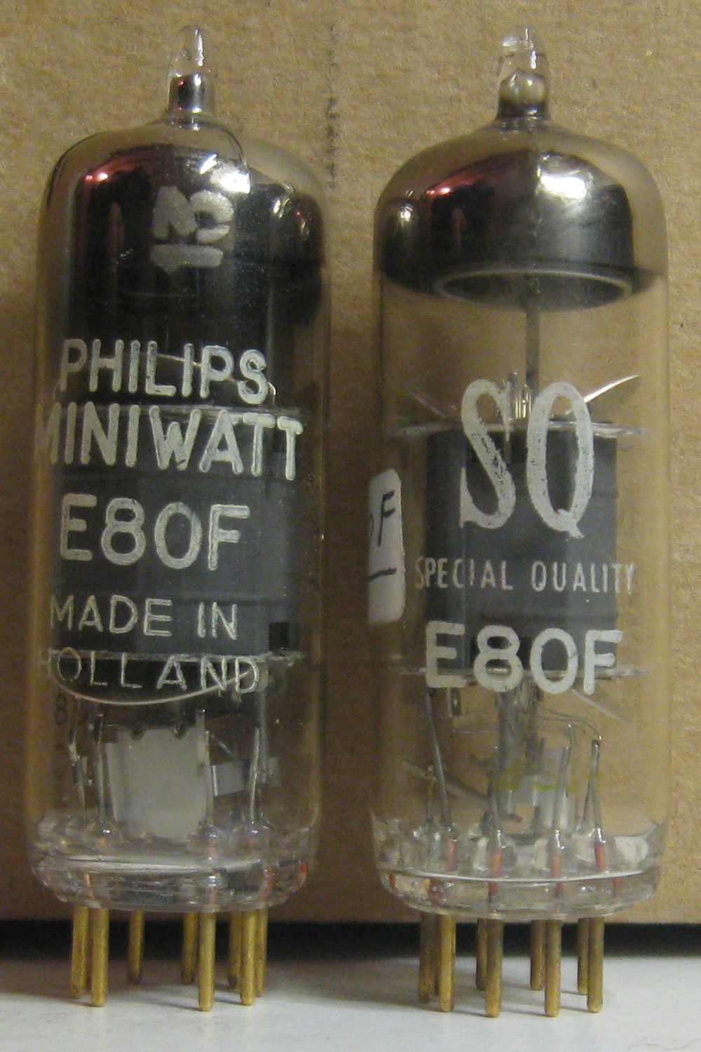
Special quality tubes were sometimes identified by placing the numerical part of the designation between the heater rating and the tube type. The special quality could be anything, from rugged designs for military and industrial use, through devices with exceptionally low noise and microphony, to designs primarily optimised for long life without cathode poisoning when used for switching in a digital computer (but not necessarily with exceptional qualities as an amplifier). For example, an ECC81 manufactured as a special quality (SQ) tube would usually be designated 'E81CC'. The system was not universal as other special quality designation systems existed. An EF91 in its special quality version was designated 'M8083' (the 'M' meant Military) as in this case the standard EF91 was derived from the M8083 military design. Also, the SQ tube was not always designed for the same tasks or given the same Maximum Ratings (for example the E80F was more suitable for audio and electrometer applications, lacking the RF screening of the EF80, with anode and screen grid power ratings roughly half the EF80.[1][2]
Two or more elements in a single envelope were handled by adding letters after the heater identifier, in alphabetical order, so an ECH35 is a 6.3 volt heated triode plus a hexode with an octal base; a PABC80 is a Noval 300mA series-heater combination of a single low-power diode A, a pair of diodes with common cathode B, and a triode C. There were many ECCnn(n) 6.3V dual triodes.
It was the usual practice for power transformers to have a 5 volt insulated winding for rectifier filaments, and a 6.3 volt winding for all the other heaters; virtually all valves with 5V filament are rectifiers with cathode connected to heater, in practice full-wave (usable as half-wave by strapping both anodes together), e.g. GZ34. For lower-voltage lower-power requirements, rectifiers with 6.3V heaters and insulated cathodes such as the EZ80 were used, connected to the common filament supply. There is no special nomenclature for EHT rectifiers for cathode-ray tubes; the EY51 and EY86 were rated at 17kV with an average current of 350 microamps.[3] The GY501 is another example (31kV at 1.7mA and used the rare B9D base).[4] In practice most "xY" half-wave rectifiers are EHT types; but there are plenty of exceptions.[5]
Symbol definitions
- 1st letter: Heater rating
- A 4V AC (See Note 1)
- B 180mA DC (See Note 1)
- C 200mA AC/DC (See Note 1)
- D 1.4V or less (normally 1.4V) or 2.8V/1.4V series/parallel filament
- E 6.3V, or 12.6V/6.3V series/parallel heater; usually AC
- F 12.6V (See Note 2)
- G Formerly 5V (often used for rectifiers) or later miscellaneous
- H 150mA AC/DC
- I 20V
- K 2V DC
- L 450mA AC/DC
- M 1.9V directly heated
- N 12.6V
- O Cold cathode (by 1955 this also included semiconductors as these had no heater)
- P 300mA AC/DC
- Q 2.4V indirectly heated
- S 1.9V indirectly heated
- T 7.4V (See Note 3)
- U 100mA AC/DC
- V 50mA AC/DC (See Note 2)
- X 600mA AC/DC
- Y 450mA AC/DC (replaced by L, to allow Y to be used for professional transmitting, microwave or industrial tubes)
- Z Cold cathode and/or gas-filled tubes
- Notes:
- Heater ratings for series-string, AC/DC tubes are given in milliamperes; heater ratings for parallel-string tubes are given in volts
- (1) Letters A,B,and C were rarely used after the 1930's and discontinued long before the 1960's and so allocated to semiconductors in the Pro Electron naming scheme
- (2) Letters F and V were so very rarely used that devices beginning with these letters (such as the FC13 Octode) should not be assumed to be part of this naming scheme.
- (3) Letter T was introduced solely for use with the TY86F EHT rectifier. This was an EY86 with a higher voltage heater specifically manufactured as a replacement for Ferguson television sets 306T and 308T manufactured in 1956. These produced excessive voltage from their line output circuits which rapidly destroyed the originally fitted EY86.[6]
- The main letters used in the second half of the Twentieth Century for receiving tubes were: D, E, G, L, P and U [7] although X was also frequently found when 600mA heater chain versions were produced for the North American market.
- Remaining letters: Type(s) of device(s)
- All except special-quality "Z" cold cathode tubes:
- A Low-current diode
- AA Low-current double diode with separate cathodes
- B Low-current double diode with common cathode
- C Small-signal vacuum triode
- D Power triode
- E Small-signal tetrode
- F Small-signal pentode
- H Hexode or Heptode (of the Hexode type)
- K Octode or Heptode (of the Octode type)
- L Power tetrode, beam tetrode or power pentode
- M Tuning indicator
- N Gas-filled triode or thyratron
- P Tube designed for secondary emission
- Q Nonode (also called Enneode[8])
- S TV sync oscillator
- T (Deflection-controlled) beam tube, or miscellaneous
- W Gas-filled halfwave rectifier
- X Gas-filled fullwave rectifier
- Y Halfwave rectifier (power diode)
- Z Fullwave rectifier (double power diode)
- All except special-quality "Z" cold cathode tubes:
- Special quality "Z" cold cathode tubes:[9]
- A Long-life amplifier tube
- B Binary counter or switching tube
- C Common-cathode Counter Dekatron that makes only carry/borrow cathodes separately available for cascading
- E Electrometer tube
- G Amplifier tube
- M Optical indicator
- S Separate-cathode Counter/Selector Dekatron that makes all cathodes available on individual pins for displaying, divide-by-n counter/timer/prescalers, etc.
- T Relay triode, a low-power triode thyratron, one starter electrode, may need illumination for proper operation if not radioactively primed
- U Low-power tetrode thyratron, may mean:
- One starter electrode and a primer (keep-alive) electrode for ion availability to keep the ignition voltage constant, for analog RC timers, voltage triggers, etc., or
- Two starter electrodes to make counters bidirectional or resettable
- W Trigger pentode, two starter electrodes and a primer electrode
- Numbers: Base type and serial number
- 1-9 Pinch-type construction valves, mostly P8 bases (P base, 8-pin side-contact) or European 5-pin (B base) and various other European pre-octal designs.
- 10–19 8-pin German metal octal, G8A
- 20–29 Loctal B8G; some octal; some 8-way side contact (exceptions are DAC21, DBC21, DCH21, DF21, DF22, DL21, DL21, DLL21, DM21 which have octal bases)
- 30–39 International Octal (IEC 67-I-5a), also known as IO or K8A
- 40–49 Rimlok (Rimlock) B8A All-glass miniature valves
- 50–59 "Special construction types fitted with bases applicable to design features used";[10] mostly locking bases: "9-pin Loctal" (B9G) or 8-pin Loctal (B8G); but also used for Octal and others (3-pin glass; Disk-seal; German 10-pin with spigot; min. 4-pin; B26A; Magnoval B9D)
- 60–64 All-glass valves fitted with 9-pin (B9G) bases
- 65-69 Sub-miniature all-glass valves with or without bases
- 70–79 Loctal Lorenz an all-glass wire (fly-leads in place of pins) subminiatures
- 80–89 Noval B9A (9-pin; IEC 67-I-12a)
- 90–99 "button" B7G (miniature 7-pin; IEC 67-I-10a)
- 100–109 B7G; Wehrmacht base; German PTT base
- 110–119 8-pin German octal; Rimlok B8A
- 130–139 Octal
- 150–159 German 10-pin with spigot; 10-pin glass with one big pin; Octal
- 160–169 Flat wire submins; 8-pin German octal
- 170–179 RFT 8-pin; RFT 11-pin all glass with one offset pin
- 180–189 Noval B9A
- 190–199 B7G
- 200–209 Decal B10B
- 230–239 Octal
- 270–279 RFT 11-pin all glass with one offset pin
- 280–289 Noval B9A
- 300–399 Octal
- 400–499 Rimlok B8A
- 500–529 Magnoval B9D; Novar
- 600–699 Flat wire-ended
- 700–799 Round wire-ended
- 800–899 Noval B9A
- 900–999 B7G
- 1000- Round wire-ended; special nuvistor
- 2000– Decal B10B
- 3000- Octal
- 5000- Magnoval B9D
- 8000- Noval B9A
- Notes:
- For signal pentodes, an odd numerical identifier most often identified a variable transconductance (remote-cutoff) valve whereas an even number identified a 'high slope' (sharp-cutoff) valve.
- For power pentodes and triode-pentode combinations, even numbers usually indicate linear (audio power amplifier) devices while odd numbers were more suited to video signals or situations where more distortion could be tolerated.
Single-digit numbers
The first types assigned using this sequence (in the mid to late 1930's) were less systematic and sometimes would append the US "G" and/or "GT" suffixes for octal base versions, although the base type was not always knowable from just the type number:
- KK2 (Cap E) was a pinch-type valve fitted with an American 7-pin base.
- Sometimes special versions were made with US (Ux-4 to 7) bases with no change in the type number (e.g. AF2, AK1, KK2), but
- in the case of Octal (IO) often a "G" would be appended to the type number; examples are ECH3G, ECH4G, EK2G, EK2G/GT, EL3G, EL3NG, KF3G, KK2G and KL4G.
- EBF2Gm EBF2GT/G and EBF35 had International Octal bases but European base connection sequences.
- Versions without the pinch at the top and/or with a metal screen might have "N" appended, and letters "A", "B" or "X" would sometimes be used for variants (e.g. AL2X, ECH33B, ECH35A, EL3N and EL3NG). The AL2X differs from the AL2 in connecting the control grid to pin 6 instead of the top cap. EL33, EL33A and EL33B are octal power pentodes differing only in whether metallization shielding is connected to pin 1 or 8.
- The AL3, AL4, EL3N and EL3NG have identical characteristics to the EL33, EL33A and EL33B but with different heater voltages and/or bases; the CL4 and CL33 are lower voltage and lower power devices that are only somewhat similar to the EL33 and PL33.
Historical progression
The older Philips system
Prior to 1934, Phillips numbers were based on a sequence of one letter to indicate filament current range, followed by one or two digits for the filament voltage, then two digits that gave either the amplification factor (for triodes) or a code beginning with 41 to indicate tetrodes, pentodes and so on.[10] Examples are:
- A409 (a 4Volt/65mA filament triode with a mu of 9)
- B2043 (a 20V/180mA indirectly-heated power output pentode from 1931)
- C243N (a 2V/200mA filament power output pentode from 1931 with the option of B5 and Ux5 bases).
Single-digit numerical sequences
An example of this format is "CL4". This format was used from 1934, when many European-specific bases existed. These bases included 5- and 8-pin side-contact, and 4- to 7-pin alternatives to incompatible US base types.[10] At this time there was pressure to produce devices compatible with wider markets, and so several versions of the same device might be produced with different bases, yet sometimes no change in type number.
Double-digit numerical sequences
An example of this designation format is "EL33A". After about 1938 the digits gave a more consistent definition of the base type. During the 1950s, most often two devices that shared the same number and all but the first letter of the name would be very similar except for heater voltage/current. During this time older filament voltage and current "families" were abandoned, so a device name beginning with "A", "B", "C" or "K" and ending in two or more digits is very unlikely to be part of this naming scheme. For example, the "KT61" is not a 2 Volt-filament beam tube within the Philips naming system, but a "kinkless tetrode" within the Marconi/EMI naming scheme.
Triple-digit numerical sequences
Examples of this format are "PL302" and "EF183". From about the start of the 1960s an extra digit was needed for new devices. Either a digit 1 was inserted before the 8 or other base-defining digit (e.g. an EF184 is a Noval pentode), or a three-digit sequence was used. For example, a PL500 is a power pentode in a Magnoval base.
Four-digit numerical sequences
Numbering using four digits were never issued under the Mullard-Philips scheme. They were obtained from the successor scheme, Pro Electron.
Semiconductors
Mullard initially handled semiconductor naming by using the "O" heater code (shifting "Cold Cathode" to a code of "Z"). From 1966 the new Pro Electron standard codified type numbers for solid-state active devices using initial letters "A", "B" and "C" (rarely used heaters) for germanium, silicon and other semiconductors. Other letters were allocated for integrated circuits. Heater letters A, B, C, F, K, V and Y ceased to be allocated for electron tube devices.
Most existing European valve type number allocations were compatible with the new system, but sometimes ambiguities could only be resolved by checking the digits in the name. For example, it might not immediately be obvious whether a (hypothetical) AD108 is a 4 volt power triode or a germanium power transistor; an AZ41 (still on sale in the 1970s[11]) might be thought to be a germanium Zener diode (although, with only 2 digits for the serial number, it was not really a valid Pro Electron designation). By the time of the introduction of the Pro Electron series most tube names started with either D, E, G, P or U, so confusion between the two systems was unlikely.
See also
References
- ↑ http://www.r-type.org/pdfs/e80f.pdf
- ↑ http://frank.pocnet.net/images/Phi/e/E80F_Phi_IMG_8200_FP.jpg Photo of E80F showing absence of RF screen, but presence of lead out scren
- ↑ The National Valve Museum: EY51
- ↑ Mazda Data Book 1968
- ↑ "Preferred Types of Electron Tubes 1967" (PDF). Retrieved 17 May 2013.
- ↑ http://www.r-type.org/exhib/aaa0834.htm
- ↑ Babani, B.B.: "Handbook of Radio, TV, Industrial & Transmitting Tube & Valve Equivalents",1974
- ↑ Philips Pocket Book, 1954, page 16
- ↑ "Cold cathode tubes ZnnnA". Retrieved 17 May 2013.
- 1 2 3 Miniwatt Technical Data, 6th Edition; 1958; Published by the "Miniwatt" Electronics Division of Philips Electrical Industries Pty. Limited, 20 Herbert Street, Artarmon, N,S,W., Australia
- ↑ Philips Pocket Book, 1973, page 13