Model 500 telephone
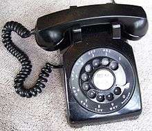
The Western Electric model 500 telephone series was the standard domestic desk telephone set issued by the Bell System in North America from 1950 through the 1984 Bell System divestiture. Millions of model 500-series phones were produced and were present in most homes in North America. Many are still in use today because of their durability and ample availability. Its modular construction compared to previous types simplified manufacture and repair, and facilitated a large number of variants with added features.
Touch-tone service was introduced to residential customers in 1963 with the model 1500 telephone, which had a push-button pad for the ten digits. The model 2500 telephone, introduced in 1968, added the * and # keys, and is still produced by several manufacturers.
History
The Western Electric 500-type telephone replaced the 300-type which had been produced since 1936. Like its predecessor, the model 500 line was designed by the firm of industrial designer Henry Dreyfuss, the product of several years of research and testing in collaboration with Bell Laboratories and Western Electric. Development started in 1946 and lead to pre-production units in 1948 and field trials with 4000 telephone sets in 1949. AT&T announced the new telephone publicly in 1949, and communicated the first availability of approximately 23,000 sets in the second quarter 1950 to the Bell System operating companies on May 1, 1950.[1] Third and fourth quarter production was estimated at 49,000 and 93,000, respectively. Including 20,000 units of a special purpose set (501B), approximately 183,000 units were produced by the end of the first production year.[2]
In the following years, systematic replacement of 25 million 300-type telephones commenced because of the much improved electrical and acoustic efficiency of the new model.[3] This efficiency permitted the new model to be used on long rural loops, which previously required special sets with local batteries to power the transmitter, not just on urban short loops, because it contained a self-adjusting gain control. This also permitted the use of thinner loop wires and thus delivered cost-savings in the build-out of the network.
The replacement of 300-series telephones with 500-series sets created large stockpiles of 300-type components that had not reached their intended service life. The accelerating demand for new telephone service in the 1950s created pressure on the manufacturing facilities, which the Bell System alleviated by reusing these older components to refurbish used 302 telephone sets with a new modern housing that had a look-alike appearance to the 500 model, but were electrically identical to the older 302 telephone. This program commenced in 1955, and the converted set was labeled as the model 5302 telephone. It was produced until the mid-1960s in the refurbishing shops of each Bell Operating Company, not on the assembly lines of Western Electric factories.
From the 1949 field trials until 1953, only black sets of the 500-type telephone were manufactured. The introduction of telephones in color occurred in several stages from 1954 until 1957, as manufacturing capability was refined and material selection processes were completed.
In the 1960s, after the introduction of touch-tone service in November 1963 in various locations of the telephone network, the basic 500-type chassis was retrofitted with a push-button keypad, along with a new housing and faceplate, creating the model 1500 for the 10-button version and in 1968 the model 2500, having 12 keys.
The 1970s brought the conversion to modular connector technology, replacing the hard-wired cords with cords terminated on both ends with 4P4C connectors for the handset cord, and 6P4C plugs for the line cord.
Ownership and AT&T divestiture
As with most telephones of the time in the United States, the 500-series telephones were owned by the local Bell Operating Company and leased on a monthly basis to customers. Choices for telephone styles and colors were limited. AT&T, the principal owner of the operating companies and Western Electric, strictly enforced policies against buying and using telephone sets by other manufacturers on their network, to ensure the technical integrity of their network and avoid competition. Most phones made by Western Electric, starting in about 1968, carried this disclaimer molded into their housing: "BELL SYSTEM PROPERTY--NOT FOR SALE." Telephones were also sometimes labeled with a sticker or ink stamp marking the name of the operating company that owned the telephone. After consumers started buying telephones from other manufacturers, in the wake of legal developments not favoring AT&T's ban against third-party equipment, AT&T changed its policy for the Design Line telephone series by selling customers the telephone housing but retaining ownership of the electrical components, so customers were still required to pay AT&T a monthly leasing fee.
In 1983, after the court ordered the Bell System divestiture, AT&T started selling telephone sets outright to the public through its newly created American Bell division. Many customers were offered the option to buy the leased telephones they had in service. AT&T closed its USA consumer telephone manufacturing plants in 1986, and moved production offshore to Singapore, China, and Thailand, and in the 1990s to Mexico; this let them produce telephones at lower cost.
Design features
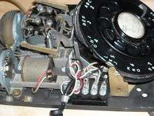
The Western Electric model 500 improved upon several design features over the earlier telephones. While the 302 had the dial and hook switch mounted directly on the metal or plastic housing, all operational parts of the 500 telephone were mounted on the base plate, and the housing only contained two plungers to activate the hook switch when the handset was lifted from the cradle. Thus, the phone could be tested and serviced easily without the housing. This design improved manufacturing and servicing efficiency. The earlier 302 had been equipped with an enamel-coated dial plate that displayed the numerals and letters through the holes of the rotary finger-wheel. Years of use caused the lettering and numbering, and even the porcelain coating, to wear off. The design of the 500 improved this by molding the characters into the plastic, through a double-injection molding process. This design was carried over to the 1500 and 2500-series telephones and was used in the touch-tone keys to eliminate wear. The numbers and letters on the 500 were moved to the circumference of the dial plate to make them clearly visible from a wide range of viewing angles even while the dial was spinning back to its resting position, and dots were placed in the center of the finger holes as targets to help position the finger quicker for dialing of the next digit while the wheel was still spinning back. After extensive testing, this arrangement had the benefit of reducing the rate of dialing errors, and increased the speed of dialing each digit by fractions of a second. The 500 series replaced many metal parts, especially in the dial, with much more durable Nylon components.
The Dreyfuss design later adapted itself well to touch-tone service, first announced in 1963. The earliest experimental touch-tone phones used the original Dreyfuss design almost unchanged; the keypad, in varying layouts, was placed in a roundel in the dial opening, with the subscriber number label in a small window below. The 1500 and 2500 models adopted a more angular design style; the curves of the original design gave way to a raised borders forming a lip around the finely-ribbed faceplate, in the middle of which the keypad and number window were centered.
Electrically and acoustically, the 500-series telephones had better efficiency and gain characteristics than their predecessors. The transmission efficiency was 5dB higher and the receiver efficiency was 2.5dB better on long loops than the 300-series telephones. A significant improvement was the use of equalization circuitry to achieve automatic gain adjustment so that the sets could be deployed with equal performance on short or long local loops from the central office. The G-type handset was newly developed to help realize this efficiency, as the older F series handset was already operating at the peak of its acoustic and electrical design efficiency. The G handset remains the standard handset on many phones, including public payphones.
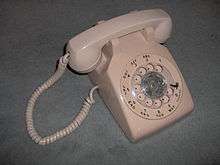
For the initial years, from 1950 to 1953, the 500 was available only in black with a metal finger wheel. In 1954, color telephone sets were available in ivory, green, gray, red, brown, beige, yellow, and blue.[4][5] Gray, blue, yellow, and red sets were initially assembled with black dials, until the colored parts became available by 1955. So called two-tone color varieties were available, which consisted of a black set having the housing substituted with a color plastic part.[4] They were offered as an attractive color combination for a reduced fee from the price of a full color telephone. In 1957, gray, blue, beige, and brown sets were replaced with lighter pastel hues in light gray, aqua blue, light beige, white, and pink colors. Issuance of brown sets, however, continued for multi-line business sets for several years. Turquoise sets were added in 1964, and several colors, including pink and light gray, were discontinued in the late 1960s.
By 1955, all color 500s were produced with clear finger wheels, while black sets retained the metal finger wheel until about 1964, when a new dial design was released.
Construction
The phone consisted of a rotary dial, a handset cradle, switch hook, and a handset (sometimes called the receiver) wired to the base, and was constructed of a molded plastic housing covering a steel chassis. The user interface consisted of only the dial and switch hook buttons. No other components, switches, or controls were necessary, with the exception of a loudness control for the ringer, which was accessible on the bottom of the phone. The handset cradle was a molded part of the housing, formed of two U-shaped chairs which cradled the handle of the handset between the receiver and the transmitter cups. Each side of the cradle had a round plastic plunger positioned above a pair of levers connected in a spring-loaded yoke that operated the hook switch; pressing the plungers down ended the call and placed the phone on-hook. The plastic face of the dial under and surrounding the finger wheel was an integral part of the dial assembly and was exposed through a large circular opening in the housing. On the bottom, the flat steel plate of the chassis was exposed. The handset cord exited from the left side of the housing at the base, and the line cord emerged from the rear at the base.
Internally, the phone contained circuitry composed of a small number of passive electrical, electronic and mechanical components. The set needed no separate power supply as it was powered from the telephone line; when it was on-hook and not ringing, it used virtually no power, as the ringer was isolated with a capacitor from the direct current (DC) potential of the local loop.
The most complex internal part was the rotary dial mechanism, an assembly of gears, cams, springs, and electrical contacts which mechanically generated a timed train of line loop-break pulses when the dial finger wheel was released after rotation. During the period of dial rotation, the receiver was shunted to avoid hearing the dialing pulses.

The ringer was a mechanical bell consisting of two bell gongs of slightly different dimensions to produce different pitches and a striker between them driven by a solenoid; when the solenoid was energized by AC ringing current, typically about 90V at 20Hz, it struck the two gongs alternately, producing a distinctive effect of two superimposed sounds. On phones with a ringer loudness control, one gong was mounted off-center on the loudness control wheel; turning the wheel moved the gong toward (quieter) or away (louder) from the striker. Overall, the model 500 ringer was fairly loud and could be heard a few rooms away. The ringer could not be turned off on-the-fly, but could be disabled in the wiring. When the phone was subjected to mechanical shock the striker would hit the brass bells and a short ring would be heard. This effect was faithfully represented in various films and television shows.
The model 500 telephone was designed for a long service life. Telephones in the Bell System were owned by and leased from the telephone company, which was responsible for keeping them in good repair. The phones were rugged and reliable, and intended to last for decades with little maintenance. The 1940s-era technology of the 500 made extensive use of metal components and point-to-point wiring, and most components were modular and easy to remove and replace. The wiring system employed wires terminated with crimped spade lugs and slotted-screw terminals; most electrical connections in the phone could be disconnected or reconnected with a standard screwdriver.
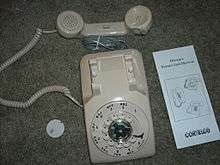
Originally, the line cord and handset cord were secured by screw-down terminals at both ends, with a strain relief anchor. Both cords had matching colors, but most color sets initially were produced with neutral, dark gray cords, with exception of the ivory and brown sets. Starting in 1955, all sets, except dark blue were equipped with color-matched cords as dyes and manufacturing methods became stable. By 1973, line cords were changed to a neutral gray color and from a round to a flat cross-section. As a customer option, telephone sets could be ordered for portability with four-prong plugs, but most sets were hard-wired to wall connection boxes. In the 1970s, much smaller modular connectors were introduced for both ends of the line cord as well as the handset cord to facilitate standard connection methods for third-party equipment within the FCC registration system.
Development

Several telephone models were derived from the basic model 500, using some of the same components. The model 554 was a wall-mounted version. Other special purpose models included additional features. This included phones with dial lights (500U), party line sets (501), keysets (540 and 560 series), call directors, panel phones (750 series), industrial and outdoor phones (520 and 525), and automatic dialers (660).[6]
Starting in 1963, the Dreyfuss design adapted itself well to the newly announced Touch Tone® service. For the trial period, the dial was simply replaced with circular closure containing a keypad and a telephone number label. The 1500 and 2500 models adopted a more rectangular design style; the curves of the original design gave way to a raised borders forming a lip around the finely-ribbed faceplate, in the middle of which the keypad and number window were centered.
Standard touch-tone telephones generate twelve DTMF signals in a grid of three columns and four rows of buttons, while some special purpose telephones are equipped with a fourth column of key for the A,B,C and D DTMF signals for service priorities in the AUTOVON system. Original sets used a transistor oscillator; newer phones use an integrated circuit. The model 1500 only had push buttons for the 10 digits, while the model 2500 used 12 keys and included the '*' and '#' DTMF signals to allow for extra signaling needed in advanced service features, such as voice response systems and call management.
Other manufacturers
Beginning in the early 1950s, 500-style phones were also made under license by ITT Kellogg (now Cortelco), who continued manufacturing the original rotary design, marketed as the Cortelco ITT-500AS (desk phone) and Cortelco ITT-554AS (wall phone), until discontinuation on January 1, 2007. The design was also produced in Canada by Northern Electric, which eventually became Northern Telecom. Cortelco continues to produce a non-dial version of the model 500, known as the Model 89001047PAK, this phone is available only in bright red color. Stromberg-Carlson (now part of Siemens) also made the phones from the 1950s-1980s.
Replicas
Some contemporary replicas of the 500 model are available. While faithful from a cosmetic point of view they are internally very different from the original, including a rotating tone dialer based on optical technology.
In popular culture
The Model 500 series, and its distinctive ring, are near-ubiquitous in late 20th-century U.S. and Canadian film and television. Perhaps attesting to their robust construction, Model 500s are shown as an effective weapon in the film True Lies.
Touch-tone successors
Model 1500

The Western Electric model 1500 telephone adapted the 500 design for touch-tone dialing with a push-button pad for the digits 0 through 9. It was produced from 1963 to 1968. In addition to the basic single-line model 1500D, the 1500-series included many related variations and special purpose models with additional features. This included sets with a headset jack, 2-line sets (1510F), key sets (1560), call directors, panel phones (1750), industrial phones (1520), and automatic dialers (1660).[7]
Model 2500
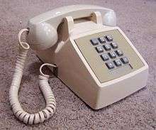
By the late 1960s interactive response systems in some industries required additional signaling beyond the ten digits. In 1968, the # key and the * key were added to the push-button dial pad, and the 2500-type telephone entered production. The additional keys were located on either side of the '0' button to fill the matrix of 4-by-3 keys. These keys were initially unused by most customers, but would later be used for vertical service codes, and voice mail menu navigation. In 1974, when modular connectors were introduced, the 2500 telephone was fitted with modular connectors for the handset cord as well as the line cord, resulting in type designations suffixed with M, e.g. 2500DM. The 2500 is still commonly encountered today and it is still produced by several companies.
In addition to the basic single-line model, the Western Electric 2500-series included many related variations and special purpose models with additional features. This included sets with a headset jack, 2-line sets, keysets (2560), call directors, panel phones (2750), industrial phones (2520), automatic dialers (2660).[8]
See also
References
- ↑ Waidlich, J.E. (May 1, 1950). "Distribution of 500-Type Telephone Sets". American Telephone and Telegraph Company. New York, NY: Telephone Collectors International. Retrieved 24 September 2013.
- ↑ Events in Telecommunications History, AT&T
- ↑ Chapuis, R.J., Joel Jr., A.E., Joel, A.E., 100 Years of Telephone Switching, IOS Press, 2003, p. 334
- 1 2 AT&T, Colored Station Sets, Bell System Practices Section C30.011, Issue 6, December 1953.
- ↑ AT&T, Telephone Sets, 500-Type, Colors, Bell System Practices Section C14.002 Issue 1 July 1955
- ↑ "Western Electric 500-series Telephone Types".
- ↑ "Western Electric 1500-series Telephone Types".
- ↑ "Western Electric 2500-series Telephone Types".
External links
- http://www.porticus.org/bell/telephones-500.html Western Electric Model 500
- http://www.arctos.com/dial/ Western Electric Telephone Models
- http://www.cortelco.com/pdf/2008SolGuide.pdf