Mineral-insulated copper-clad cable
| Wikimedia Commons has media related to Mineral Insulated Copper-Clad Cables. |
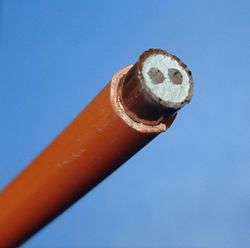
Mineral-insulated copper-clad cable is a variety of electrical cable made from copper conductors inside a copper sheath, insulated by inorganic magnesium oxide powder. The name is often abbreviated to MICC or MI cable, and colloquially known as pyro (because the original manufacturer and vendor for this product in the UK was a company called Pyrotenax). A similar product sheathed with metals other than copper is called mineral insulated metal sheathed (MIMS) cable.
MI cable is made by placing copper rods inside a circular copper tube and filling the intervening spaces with dry magnesium oxide powder. The overall assembly is then pressed between rollers to reduce its diameter (and increase its length). Up to seven conductors are often found in an MI cable, with up to 19 available from some manufacturers.
Since MI cables use no organic material as insulation (except at the ends), they are more resistant to fires than plastic-insulated cables. MI cables are used in critical fire protection applications such as alarm circuits, fire pumps, and smoke control systems. In process industries handling flammable fluids MI cable is used where small fires would otherwise cause damage to control or power cables. MI cable is also highly resistant to ionizing radiation and so finds applications in instrumentation for nuclear reactors and nuclear physics apparatus.
The metal tube shields the conductors from electromagnetic interference. The metal sheath also physically protects the conductors, most importantly from accidental contact with other energised conductors.
MI cables may be covered with a plastic sheath, coloured for identification purposes. The plastic sheath also provides additional corrosion protection for the copper sheath.
History
The first patent for MI cable was issued to the Swiss inventor Arnold Francois Borel in 1896. Initially the insulating mineral was described in the patent application as pulverised glass, silicious stones, or asbestos, in powdered form. Much development ensued by the French company Société Alsacienne de Construction Mécanique.[1] Commercial production began in 1932 and much mineral-insulated cable was used on ships such as the Normandie and oil tankers, and in such critical applications as the Louvre museum. In 1937 a British company Pyrotenax, having purchased patent rights to the product from the French company, began production. During the Second World War much of the company's product was used in military equipment.
About 1947 the British Cable Maker's Association investigated the option of manufacturing a mineral-insulated cable that would compete with the Pyrotenax product. The manufacturers of the products "Bicalmin" and "Glomin" eventually merged with the Pyrotenax company.
The Pyrotenax company introduced an aluminum sheathed version of its product in 1964. MI cable is now manufactured in several countries. Pyrotenax is now a brand name under Pentair Thermal Management.
Purpose and use
MI cables are used for power and control circuits of critical equipment, such as the following examples:
- Nuclear reactors
- Exposure to dangerous gasses
- Air pressurisation systems for stairwells to enable building egress during a fire
- Hospital operating rooms
- Fire alarm systems
- Emergency power systems
- Emergency lighting systems
- Temperature measurement devices; RTDs and Thermocouples.
- Critical process valves in the petrochemical industry
- Public buildings such as theatres, cinemas, hotels
- Transport hubs (railway stations, airports etc.)
- Mains supply cables within residential apartment blocks
- Tunnels and mines
- Electrical equipment in hazardous areas where flammable gases may be present e.g. oil refineries, petrol stations
- Areas where corrosive chemicals may be present e.g. factories
- Building plant rooms
- Hot areas e.g. power stations, foundries, and close to or even inside industrial furnaces, kilns and ovens
MI cable fulfills the passive fire protection called circuit integrity, which is intended to provide operability of critical electrical circuits during a fire. It is subject to strict listing and approval use and compliance
Heating cable
A similar appearing product is mineral-insulated trace heating cable, in which the conductors are made of a high-resistance alloy. A heating cable is used to protect pipes from freezing, or to maintain temperature of process piping and vessels. An MI resistance heating cable may not be repairable if damaged. Most electric stove and oven heating elements are constructed in a similar manner.
Typical specifications
| maximum voltage | 600 or 1000 volts | |||||||||
| current rating | 18 - 450 amperes | |||||||||
| conductor area | 1.0 – 240 mm² | |||||||||
| copper sheath area | 5 – 70 mm² effective | |||||||||
| number of cores | 1,2,3,4,7,12,19 | |||||||||
| overall diameter | 5 – 26 mm | |||||||||
| minimum bend radius | 6 x diameter (3 x diameter if bent once only) | |||||||||
| weight | 100 – 3300 kg/km, 355 - 11708.4 lbs/mi | |||||||||
| twists per metre | 0, 20; In many applications NO twist is preferred. | |||||||||
| finish | bare copper, standard PVC sheath, low smoke and fume (LSF) polymer sheath, various Stainless Steels, Inconel, Titanium, and some super alloys. | |||||||||
| colour | natural (Bare Stainless, bare copper), white, black, red, orange | |||||||||
| maximum operating temperature |
|
Advantages
The metal sheath and solid filling of MI cable makes it mechanically robust and resistant to impact; an MI cable may be struck repeatedly with a hammer and still provide adequate insulation resistance for a circuit.[2] Copper sheathing is waterproof and resistant to ultraviolet light and many corrosive elements. MI cable is approved by electrical codes for use in areas with hazardous concentrations of flammable gas in air; an MI cable will not allow propagation of an explosion inside the copper tube, and the cable is unlikely to initiate an explosion even during circuit fault conditions. Metal sheathing will not contribute fuel or hazardous combustion products to a fire, and cannot propagate a fire along a cable tray or within a building. The cable is inherently fire-rated without additional coatings, and will survive designated fire tests representative of actual fire conditions longer than the enclosing structure.
When used within a tenanted area, carrying electricity supplied and billed to the landlord, for example for a communal extract system or antenna booster, it provides a supply cable that cannot easily be 'tapped' into to obtain free energy.
Although made from solid copper elements, the finished cable assembly is still pliable due to the malleability of copper. The cable can be bent to follow shapes of buildings or bent around obstacles, allowing for a neat appearance when exposed.
Since the inorganic insulation does not degrade with (moderate) heating, the finished cable assembly can be allowed to rise to higher temperatures than plastic-insulated cables; the limits to temperature rise may be only due to possible contact of the sheath with people or structures. This may also allow a smaller cross-section cable to be used in particular applications.
Due to oxidation, the copper cladding darkens with age and MICC is therefore often used in historic buildings such as castles where it blends in with stonework. However, where MICC cables with a bare copper sheath are installed in damp locations, particularly where lime mortar has been used, the water and lime combine to create an electrolytic action with the bare copper. Similarly, electrolytic action may also be caused by installing bare-sheath MICC cables on new oak. The reaction causes the copper to be eaten away, making a hole in the side of the cable and letting in water, causing a short-circuit between live, neutral and earth. The appearance of green verdigris on the bare copper sheath may be a sign this has occurred.
Disadvantages
- The termination points: While the length of the MI cable is very tough, at some point, each run of cabling terminates at a splice or within electrical equipment. These terminations are vulnerable to fire, moisture, or mechanical impact.
- Vibration: MICC is not suitable for use where it will be subject to vibration or flexing, for example connection to heavy or movable machinery. Vibration will crack the cladding and cores, leading to failure.
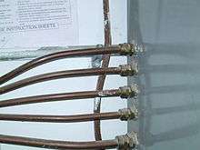
- Labour Cost: During installation MI cable must not be bent repeatedly as this will cause work hardening and cracks in the cladding and cores. A minimum bend radius must be observed and the cable must be supported at regular intervals. The magnesium oxide insulation is hygroscopic so MICC cable must be protected from moisture until it has been terminated. Termination requires stripping back the copper cladding and attaching a compression gland fitting. Individual conductors are insulated with plastic sleeves. A sealing tape, insulating putty or an epoxy resin is then poured into the compression gland fitting to provide a watertight seal. If a termination is faulty due to workmanship or damage then the magnesium oxide will absorb moisture and lose its insulating properties. Depending on the size and number of conductors, a single termination can take between 1 and 2 hours of labour (an electrician should be able to make a termination in 10 to 15 minutes on up to 4 core smaller sizes). Installation of a three-conductor MI cable (size No. 10 AWG — about 5 square mm) takes about 65% more time than installation of a PVC-sheathed armoured cable of the same conductor size.[3] Installation of MICC is therefore a costly task. Certain PTFE, silicone or other polymer-insulated cables have been substituted in applications which require similar properties in terms of flame spread, which use less labour to terminate. MICC is still used in applications which are particularly suited to its combination of properties.
- Voltage rating: MI cable is only manufactured with ratings up to 1000 volts.
- Moisture absorption: The magnesium oxide insulation has a high affinity for moisture. Moisture introduced into the cable can cause electrical leakage from the internal conductors to the metal sheath. Moisture absorbed at a cut end of the cable may be driven off by heating the cable.
- Corrosion: The copper sheath material is resistant to most chemicals but can be severely damaged by ammonia-bearing compounds and urine. A pinhole in the copper sheathing will allow moisture into the insulation, and eventual failure of the circuit. A PVC over jacket or sheaths of other metals may be required where such chemical damage is expected. When MI cable is embedded in concrete as snow melting cable it is subject to physical damage by concrete workers working the concrete into the pour. If the 3-5mil coating is damaged pin holes in the copper jacket develop causing premature failure of the snow melting system.
- Repair: If the MI cable jacket has been damaged the magnesium oxide will wick moisture into the cable and it will lose its insulating properties causing shorts to the copper cladding, and thence to earth. It is often necessary to remove 0.5 to 2 metres (1.6 to 6.6 ft) of the MI cable and splice in a new section to accomplish the repair. Depending on the size and number of conductors, a single termination can take between one and two hours of labour.[3]
Alternatives
Circuit integrity for conventional plastic-insulated cables requires additional measures to obtain a fire-resistance rating or to lower the flammability and smoke contributions to a minimum degree acceptable for certain types of construction. Sprayed-on coatings or flexible wraps cover the plastic insulation to protect it from flame and reduce its flame spreading ability. However, since these coatings reduce the heat dissipation of the cables, often they must be rated for less current after application of fire-resistant coatings. This is called current capacity derating. It can be tested through the use of IEEE 848 Standard Procedure for the Determination of the Ampacity Derating of Fire-Protected Cables.
See also
- Listing and approval use and compliance
- Passive fire protection
- Circuit integrity
- Fireproofing
- Cable tray
- Copper wire and cable
References
- ↑ Robert M. Black, The History of Electric Wires and Cable, Peter Peregrinus Ltd.London, 1983 ISBN 0-86341-001-4, pgs. 158-159
- ↑ Fire Performance Test for Fire Survivable Cables. http://www.fire-cables.co.uk/fire_performance.html
- 1 2 R.S. Means Co, Electrical Cost Data 22nd Annual Edition, 1999, ISBN 0-87629-504-9
External links
- https://www.wrexhammineralcables.com Wrexham mineral cables, a manufacturer of MICC cable in the UK