Microwave imaging
Microwave imaging is a science which has been evolved from older detecting/locating techniques (e.g., radar) in order to evaluate hidden or embedded objects in a structure (or media)using electromagnetic (EM) waves in microwave regime (i.e., ~300 MHz-300 GHz).[1] Microwave imaging techniques can be classified as either quantitative or qualitative.[2] Quantitative imaging techniques (are also known as inverse scattering methods) give the electrical (i.e., electrical and magnetic property distribution) and geometrical parameters (i.e., shape, size and location) of an imaged object by solving a nonlinear inverse problem.[3] The nonlinear inverse problem is converted into a linear inverse problem (i.e., Ax=b where A and b are known and x (or image) is unknown) by using Born or distorted Born approximations. Despite the fact that direct matrix inversion methods can be invoked to solve the inversion problem, this will be so costly when the size of the problem is so big (i.e., when A is a very dense and big matrix). To overcome this problem, direct inversion is replaced with iterative solvers. Techniques in this class are called forward iterative methods which are usually time consuming.[4] On the other hand, qualitative microwave imaging methods calculate a qualitative profile (which is called as reflectivity function or qualitative image) to represent the hidden object. These techniques use approximations to simplify the imaging problem and then they use back-propagation (also called time reversal, phase compensation, or back-migration) to reconstruct the unknown image profile. Synthetic aperture radar (SAR), ground-penetrating radar (GPR), and frequency-wave number migration algorithm are some of the most popular qualitative microwave imaging methods[1].
Principles
In general, a microwave imaging system has two parts, namely: hardware and software (or post-processing). The hardware part is responsible to collect data from the sample under test. A transmitter antenna sends EM waves toward sample under test (e.g., human body for medical imaging). If the sample is made of only homogeneous material which extends to infinity, theoretically no EM wave will be reflected. Introduction of any anomaly which has a different properties (i.e., electrical/magnetic)in comparison with the surrendering homogeneous medium may reflect a portion of EM wave. The bigger the difference between the properties of the anomaly and the surrounding medium is, the stronger the reflected wave will be. This reflection will be collected and measured by the same antenna (in monostatic case) or a different receiver antenna (in bistatic case).
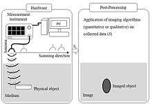
To increase cross-range resolution of the imaging system, several antennas should be distributed over an area (which is called sampling area) with a spacing less than the operating wavelength. However, by having several antennas placed close to each other, the mutual coupling between antennas may degrade the accuracy of the collected signals. Moreover, transmitter and receiver system will become very complex. To address these problems, one single scanning antenna is used instead of several antennas. Later, when the antenna finishes scanning the entire sampling area, one can put together collected data all over the sampling area and process them together, simultaneously. In fact, a synthetic (virtual) aperture is produced by moving the antenna (similar to synthetic aperture radar principle[5]). Later, the collected data, which is sometimes referred to as raw data, is fed into the software for processing. Based on applied processing algorithm, microwave imaging techniques can be categorized as quantitative and qualitative.
Applications
Microwave imaging has been used in a variety of applications such as: nondestructive testing and evaluation (NDT&E), medical imaging, concealed weapon detection at security check points, structural health monitoring, and through-the-wall imaging. Some of the recent applications of microwave imaging for NDT&E can be listed as:[6] a) disbond detection in strengthened concrete bridge members retrofitted with carbon fiber reinforced (CFRP) composite laminates, b) Corrosion and precursor pitting detection in painted aluminum and steel substrates, c)Flaw detection in spray-on foam insulation and the acreage heat tiles of the Space Shuttle.
Microwave imaging for medical applications is also becoming of more interest. The dielectric properties of malignant tissue change significantly in comparison with the properties of normal tissue (e.g., breast tissue). This difference translates into a contrast which can be detected by microwave imaging methods. As one example, there are several research groups all around the world working on developing efficient microwave imaging techniques for early detection of breast cancer.[7]

Ageing of infrastructure is becoming a serous problem worldwide. For example, in reinforced concrete structures, corrosion of their steel reinforcements is the main cause of their deterioration. In U.S. alone, repair and maintenance cost due to such corrosion is about $276 billion per year,[8] [3].
Recently, microwave imaging has shown great potential to be used for structural health monitoring. Lower frequency microwaves (e.g., <10 GHz) can easily penetrate through concrete and reach objects of interest such as reinforcement bars (rebars). If there is any rust on the rebar, since rust reflects less EM waves in comparison with sound metal, the microwave imaging method can distinguish between rebars with and without rust (or corrosion). Microwave imaging also can be used to detect any embedded anomaly inside concrete (e.g., crack or air void).
References
- ↑ "Synthetic aperture radar-based techniques and reconfigurable antenna design for microwave imaging of layered structures". hdl.handle.net. Retrieved 2014-05-07.
- ↑ L. Lianlin, W. Zhang, and F. Li, “Derivation and Discussion of the SAR Migration Algorithm Within Inverse Scattering Problem: Theoretical Analysis,” IEEE Trans. Geosci. Remote Sens. E, vol. 48, no. 1, pp. 415–422, Jan. 2010.
- ↑ M. Fallahpour, J.T. Case, M. Ghasr, and R. Zoughi, “Piecewise and Wiener Filter-Based SAR Techniques for Monostatic Microwave Imaging of Layered Structures”, IEEE Transactions on Antennas and Propagation, vol. 62, no. 1, pp. 1-13, Jan. 2014.
- ↑ J. De Zaeytijd, A. Franchois, C. Eyraud, and J.-M. Geffrin, “Fullwave Three-Dimensional Microwave Imaging with a Regularized Gauss–Newton Method—Theory and Experiment,” IEEE Trans. Antennas Propag., vol. 55, no. 11, pp. 3279–3292, Nov. 2007.
- ↑ M. Soumekh, Synthetic Aperture Radar Signal Processing, 1st ed. New York, NY, USA: Wiley, 1999.
- ↑ S. Kharkovsky and R. Zoughi, “Microwave and millimeter wave nondestructive testing and evaluation—Overview and recent advances,” IEEE Instrum. Meas. Mag., vol. 10, pp. 26–38, Apr. 2007.
- ↑ Bond E J, Li X, Hagness S C and Van Veen B D 2003 Microwave imaging via space-time beamforming for early detection of breast cancer IEEE Trans. Antennas Propagat. 51 1690-705
- ↑ G. Roqueta, L. Jofre, and M. Feng, “Microwave Non-Destructive evaluation of corrosion in reinforced concrete structures,” in Proc. 5th Eur. Conf.Antennas Propagation (EUCAP),Apr. 11–15, 2011, pp. 787–791.