Mast radiator
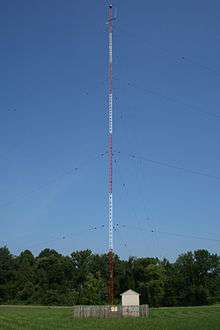
A mast radiator (or 'radiating tower') is a radio mast or tower in which the entire structure functions as an antenna. This design, developed around 1930, is commonly used for transmitting antennas operating at low frequencies, in the VLF, LF and MF ranges, in particular those used for AM broadcasting. The metal mast is electrically connected to the transmitter. Its base is usually mounted on a nonconductive support to insulate it from the ground. A mast radiator is a form of monopole antenna.
Design considerations
Design

Most mast radiators are built as guyed masts insulated from the ground at the base. Steel lattice masts of triangular cross-section are the most common type. Square lattice masts and tubular masts are also sometimes used. To ensure that the tower is a continuous conductor, the tower's structural sections are electrically bonded at the joints by short copper jumpers which are soldered to each side.
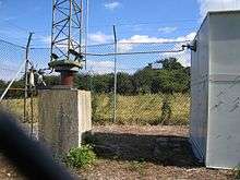
At its base, the mast is usually mounted on a thick ceramic insulator, which has the compressive strength to support the tower's weight and the dielectric strength to withstand the high RF voltage applied by the transmitter. The RF power to drive the antenna is supplied by an antenna tuner unit, usually housed in a small building called a helix building next to the mast, and the cable supplying the current is simply bolted to the tower. The actual transmitter is usually located in a separate building, which supplies RF power to the helix building via a transmission line.

Free-standing towers are also used as radiating structures. These towers can have a triangular or a square cross section, with each leg supported on an insulator. One of the best-known radiating towers is the Blosenbergturm in Beromünster, Switzerland. Fiberglass masts are sometimes used for small constructions.
Mast height
The ideal height of a mast radiator depends on transmission frequency, demographics for the location, and terrain. For radio systems in the longwave and mediumwave range, the value of the height should be in the range between one sixth and five eighths of the wavelength, with preferred values at the quarter or the half of the radiated wavelength. When this is not possible, masts with a loading coil, 'capacity hat' or similar loading arrangement are used.
The height of the mast determines the radiation properties. For high power transmitters in the MW range, masts with heights around half of the radiated wavelength are preferred because they focus the radiated power better to the ground than structures with heights of quarter wavelengths, which are preferred for economical reasons for low power medium wave transmitters. A focus of radiated power towards the ground is much desired on frequencies below 3 megahertz, because groundwave propagation is very stable. Masts longer than five eighths of the wavelength are normally not used, because they show bad vertical radiation patterns, so masts for mediumwave transmitters do not normally exceed 300 metres. For longwave transmitters, however, the construction of masts with heights of half-wave wavelength is generally not economically viable and in most cases impossible. The only longwave radio mast with a height of the half length of the radiated wavelength was the Warszawa Radio Mast at Konstantynów, Poland. At the time of its collapse in 1991 it was the tallest manmade structure in the world, at 646.38 metres (2,120.67 ft) tall, for a wavelength of 1292.76 metres (frequency 232 kHz). For frequencies below longwave, masts are electrically enlarged by loading coils or capacity hats on the top, because masts of even quarter wavelength would be too high to be practical.
Feed arrangements


There are three ways of feeding a mast radiator from a transmitter:
- Series excited: the mast is supported on an insulator, and the transmitter is connected to the mast just above it;
- Shunt excited: the mast is grounded and the transmitter feeds it via a wire connected to the mast part way up. (This is a similar approach, on a larger scale, to the 'gamma match' popular among amateur radio operators for VHF and UHF amateur radio antennas.)
- Sectional: the structure is divided into usually two sections with insulators between, usually center-fed. This collinear arrangement enhances low-angle (ground wave) radiation and reduces high-angle (sky wave) radiation. This increases the distance to the mush zone where the ground wave and sky wave are at similar strength at night. This type of antenna is known as an anti-fading aerial. Practical sectionals with 120 over 120 degrees, 180 over 120 degrees and 180 over 180 degrees are presently in operation with good results.
There is usually an antenna matching unit to match the impedance of the transmitter or feeder to the antenna. Depending on the power involved, this may be a small box or a hut or building. It will typically contain an L-network to transform the modulus of impedance, and a coil or capacitor in series with the mast connection to 'tune out' any reactive component.
Location on transmission facility
At some facilities, especially the older and higher-powered installations, the mast radiator may be located at some distance from the transmitter building, in order to reduce the field strength induced by the mast into the building, and to prevent the building from distorting the mast's radiation pattern. Between the transmitter building and the antenna matching unit next to the mast radiator, there is a feeder: either an underground coaxial cable or an overhead wire 'cage' feeder.
At facilities with multiple masts, spacings are typically smaller, in order to fit them into the available space.
At modern transmitters or at low power transmitters situated in very small transmitter buildings the transmitter, matching unit and mast radiator can be very close together and even in the same building. This measure saves on feeders, land area and increases the efficiency of the transmitter if only one mast radiator is in use.
At most facilities the mast radiator is on a separate base close to the antenna matching unit, but it can be sometimes be placed on the roof of the antenna matching unit, for example at the main transmission mast of the Mühlacker radio transmitter and the main transmission mast of the Ismaning radio transmitter.
For a good groundwave propagation, mast radiators are built on a large flat area with good ground conductivity and if possible without inclination. The construction of a mast radiator on the top of a building or tower whose height is in the same magnitude range as the wavelengths being transmitted gives a bad groundwave propagation. For this reason, mast radiators are (in contrast to FM broadcasting antennas) not typically installed on the top of buildings or towers. Nevertheless in rare cases, mast radiators for low power transmissions are installed on top of buildings. Some lighthouses, such as Reykjanesviti carry a mast radiator for a longwave radio beacon on the roof. The best-known are WGSO in New Orleans and KSBN (AM) on the Delaney Building in Spokane, Washington. In Europe, the low-power broadcasting station at Campobasso uses a mast radiator on a castle.
Fencing
Mast radiators, as with all other equipment showing over 42 volts on exposed components within 4 metres of the ground, are required to be fenced in. Usually a chain-link fence is used, but sometimes wooden fences are used in order to prevent signal interference, which could occur due to currents induced by radio signals in metallic fences. If the mast radiator is mounted on the top of the helix building, which must be over four metres in height; or the mast is grounded, with the feed being located not less than four metres above the ground, a fence is not required. Nevertheless it is always recommended to fence in any mast radiator in order to prevent unauthorized climbing.
Ancillary connections
A mast radiator may need various electrical connections other than the transmitter feed line. Such connections include static drain chokes (which drain off static charges caused by wind, clouds, etc.), spark-gap balls for lightning protection, power supplies for aircraft warning lamps, and coaxial feeders for ancillary antennas mounted on the mast. A variety of techniques are used to 'isolate' these connections from the high RF voltage on the mast, such as chokes, parallel tuned circuits and coupling loops, on a base-fed mast. On a shunt-fed mast, where the base is grounded, such measures are unnecessary.
Anti-fading antennas

An anti-fading antenna (informally and often incorrectly termed a "Franklin" antenna) is a long- and medium-wave transmission antenna with a flat vertical radiation pattern. The design goal is to move the mush zone farther from the transmitter site. An anti-fading antenna will reduce radiation at elevations of more than 50 degrees as much as possible. In principle, such a radiator should be as thin as possible, although thicker radiators improve the bandwidth and contribute to a taller effective height.
These antennas are usually constructed using a metal radio mast, which is fed both at its base and at an appropriate height. The radio mast is usually insulated from ground and is divided electrically by a separation insulator into two parts. For feeding of the upper part, either a cable inside the mast construction or the ladder, which must be mounted on insulators, is used. This design is employed in the Mühlacker, Wolfsheim and Hamburg medium-wave transmitters. Anti-fading antennas with two separation insulators are installed at Ismaning.
Because separation insulators are fragile compared to the construction of the radio mast framework, horizontal forces, such as those generated by wind-caused oscillations, need to be minimized. Radio masts with built-in separation insulators may employ oscillation dampers just above the separation insulator. This approach is used on the radio masts of Wolfsheim, Hamburg and Ismaning.
A simple anti-fading antenna is a vertical radiator whose height is between 1/2 wavelength (180 electrical degrees) and 5/9 wavelength (200 degrees), 195 degrees being considered ideal. 200 degree and taller simple radiators have largely fallen into disuse, although these can be useful on medium power stations, in which case radiators as tall as 5/8 wavelength (225 degrees) are somewhat common. Any simple radiator (or array of radiators) which is taller than 195 degrees is generally not considered to have anti-fading properties.
A more complex anti-fading antenna is a vertical radiator which is sectionalized and is one wavelength (360 degrees, generally 180 over 180 degrees, and historically and correctly termed a "Franklin" radiator; two in an array at KFBK), or 300 degrees (180 over 120 degrees, and formally called a WHO radiator), or 240 degrees (120 over 120 degrees, and formally called a WOAI radiator, but WOAI has since replaced this with a 195 degree radiator for lower maintenance cost at the expense of somewhat poorer "fringe" reception). Several have been incorporated into phased arrays (directional antennas). When so sectionalized the sections are themselves phased so as to provide the optimum vertical radiation pattern (suppressing high-angle radiation). An advantage of the 180 over 180 degree configuration is no ground radial system is required, and the bottom of the lower section may be insulated from the ground; for the others, the bottom of the lower section is usually connected to a ground radial system through a capacitor.
Another form of anti-fading mast antenna is a circular array antenna, in which a number of mast radiators are arranged on a circle and fed in equal phase. With this design, very flat radiation patterns may be produced, although they are very expensive since multiple radio masts are required. Taldom transmitter and Tulagino transmitter in Russia are currently the only radio stations in the world using such antennas. At one time, longwave transmitter Orlunda in Sweden also used an antenna of this type.
Records
The tallest mast radiator ever built was the Warsaw radio mast at Konstantynow, Poland. The antenna was 648.38 metres (2,127.2 ft) high but collapsed in 1991. Currently the masts of the Lualualei VLF transmitter, at 458.11 metres (1,503.0 ft), are the tallest mast radiators insulated against ground. In contrast to the Warsaw Radio Mast, the Lualualei antenna uses extensive electrical lengthening measures. The tallest mast radiator not using electrical lengthening may be the Hellissandur longwave radio mast at 411.48 metres (1,350.0 ft) high.