Magnifying transmitter
The magnifying transmitter is an advanced version of Tesla coil transmitter. It is a high power harmonic oscillator that Nikola Tesla intended for the wireless transmission of electrical energy. In his autobiography, Tesla stated that ". . . I feel certain that of all my inventions, the Magnifying Transmitter will prove most important and valuable to future generations."[1] The magnifying transmitter is an air-core, multiple-resonant transformer that can generate very high voltages.
History
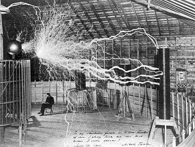
The first "Magnifier" was assembled in New York City between 1895 - 1898.[1] In 1899 a larger magnifier was constructed in Colorado Springs, Colorado. This machine was used to conduct fundamental experiments in wireless telecommunications and electrical power transmission. Measuring fifty-one feet (15.5 m) in diameter, it developed a working potential estimated at 3.5 million to 4 million volts and was capable of producing electrical discharges exceeding one hundred feet (30 m) in length.[2]
Colorado arrival


In 1899, Tesla moved his research to Colorado Springs. He chose this location because the polyphase alternating current power distribution system had been introduced there and he had associates who were willing to give him all the power he needed without charging for it.[3] He kept a handwritten diary of his experiments in the Colorado Springs lab where he spent nearly nine months. It consists of 500 pages of notes and nearly 200 drawings, recorded chronologically between June 1, 1899 and January 7, 1900, as the work occurred, containing explanations of his experiments.
Tuned electrical circuits
While in Colorado, Tesla constructed many smaller resonance transformers and conducted further research on concatenated tuned electrical circuits. Tesla also designed various sensitive devices for detecting received electrical energy, including rotating coherers. These used a clockwork mechanism of gears driven by a coiled spring-drive which rotated a small glass cylinder containing metal filings. These experiments were the final stage after years of work on synchronized tuned electrical circuits. These instruments were constructed to demonstrate how a wireless receiver could be "tuned" to respond to a specific complex signal while rejecting others. Tesla logged in his diary on January 2, 1900 that a separate resonance transformer tuned to the same high frequency as a larger high-voltage resonance transformer (which acted as a transmitter) received energy from the larger coil, one of many demonstrations of the wireless transmission of electrical energy.
Energy transmission
On July 3, 1899, Tesla claimed to have discovered "terrestrial stationary waves", standing waves extending across the earth to the antipode opposite his transmitter. He also claimed according to his measurements that Earth behaved as a smooth polished conductor of very low resistance, and that it responded to certain predescribed frequencies of electrical vibrations. Tesla researched ways to transmit energy wirelessly over long distances, first by transverse waves, and then, according to him, by longitudinal waves. He used this research to generate patents on what he thought was a wireless transmission method of generating standing waves of electrical energy within the Earth.
The magnifying transmitter was the basis for Tesla's later Wardenclyffe Tower project. Although modern Tesla coils are designed to generate spark discharges, this system was designed for wireless telecommunications and electrical power transmission. In 1925, John B. Flowers advanced a proposal to test Tesla's system and to implement the system. H. L. Curtis, the chief of the Bureau of Standards Radio Laboratory in Washington D.C., and J. H. Dillinger, a physicist, reviewed the proposal but declined to implement the proposed plan. Flowers's mechanical analogy test was successful, though.[4]
Electromechanical oscillator
Tesla developed the reciprocating electro-mechanical oscillator as a source of frequency stable or isochronous alternating electric current used in conjunction with both wireless transmitting and receiving apparatus. This circuit element was applied in the same manner as quartz crystal oscillators are now. He also proposed the use of this device for geophysical exploration by means of seismology—a technique that he called telegeodynamics.
Magnifying transmitter and the Wardenclyffe Tower
Transmitter details
|
The layout of the Wardenclyffe magnifying transmitter is well known, based upon Tesla's patents[5][6] and various photographs[7][8] in which the concept was implemented. The Wardenclyffe magnifying transmitter was not identical to the classic Tesla coil. It had the short thick primary and secondary inductor characteristic of the Tesla coil, although magnetic coupling between the two was tighter. Because of this, more aggressive measures had to be taken in terms of primary spark quenching and providing additional insulation between the primary and secondary. In addition to these two large-diameter coils that comprise the master oscillator at Wardenclyffe, Tesla added a third inductor called the "extra coil."
Construction and theory of operation
In a classic Tesla coil the primary drives the ground end of the secondary coil to form the driver transformer, which resonates the entire secondary coil. In the magnifying transmitter the driving and resonating parts of the secondary are separate coils. From a circuit analysis standpoint, there is little difference between the classic coil and the magnifier.
The extra coil or helical resonator can be physically separated from the two close-coupled coils, which comprise the master oscillator or driver section. The power from the master oscillator is fed to the lower end of the extra coil resonator through a large diameter electrical conductor or pipe to minimize corona discharge. The magnifying transmitter's base-driven extra coil behaves as a slow-wave helical resonator, the axial disturbance propagating at a velocity of less than 1% up to around 10% the speed of light in free space. The axial velocity of the resonator's charge-coupled electromagnetic field is established by the coil pitch and electrical charge propagation speed through the circuit.
Operation
At Colorado Springs, Tesla used his magnifying transmitter in an attempt to stimulate terrestrial standing waves. Based upon observations made with the device, Tesla reported that an earth resonance mode involving an electric current flowing through the earth can be excited. He claimed to have discovered a fundamental earth resonance frequency of approximately 11.787 Hz, significantly higher than the fundamental earth-ionosphere cavity Schumann resonance in the vicinity of 7.3 Hz, found to exist by researchers in the 1950s.
In normal operation the magnifying transmitter is relatively silent, generating a high power electric field, but if the output voltage exceeds the design voltage of the elevated terminal, high-voltage sparks will strike out from the electrode into the air.
Related Tesla patents
- "System of Electric Lighting," U.S. Patent 454,622, 23 June 1891
- "Means for Generating Electric Currents," U.S. Patent 514,168, 6 February 1894
- "Electrical Transformer," U.S. Patent 593,138, 2 November 1897
- "Method of and Apparatus for Controlling Mechanism of Moving Vehicle or Vehicles ", U.S. Patent 613,809, 8 November 1898
- "Apparatus for Transmission of Electrical Energy," U.S. Patent 649,621, 15 May 1900
- "System of Transmission of Electrical Energy," U.S. Patent 645,576, 20 March 1900
- "Apparatus for Utilizing Effects Transmitted from a Distance to a Receiving Device through Natural Media," U.S. Patent 685,953, Nov. 5, 1901
- "Method of Utilizing Effects Transmitted through Natural Media," U.S. Patent 685,954, Nov. 5, 1901
- "Apparatus for Utilizing Effects Transmitted From A Distance To A Receiving Device Through Natural Media," U.S. Patent 685,955, Nov. 5, 1901
- "Apparatus for Utilizing Effects Transmitted through Natural Media," U.S. Patent 685,956, Nov. 5, 1901
- "Method Of Utilizing Radiant Energy," U.S. Patent 685,958, 5 November 1901
- "Method of Signaling," U.S. Patent 723,188, Mar. 17, 1903
- "System of Signaling," U.S. Patent 725,605, Apr. 14, 1903
- "Art of Transmitting Electrical Energy through the Natural Mediums," U.S. Patent 787,412, Apr. 18, 1905
- "Apparatus for Transmitting Electrical Energy," Jan. 18, 1902, U.S. Patent 1,119,732, Dec. 1, 1914
See also: List of Tesla patents
See also
- Electromechanical oscillator
- Magnifying Transmitter as described by Tesla in his Autobiography
- Cavity resonator
- Knob Hill
- Longitudinal wave
- Telluric current
- Wardenclyffe Tower
- World Wireless System
References
- 1 2 My Inventions: The Autobiography of Nikola Tesla, Hart Brothers, 1982, Ch. 5, ISBN 0-910077-00-2
- ↑ Nikola Tesla: Guided Weapons & Computer Technology, Leland I. Anderson, 21st Century Books, 1998, pp. 12-13, ISBN 0-9636012-9-6.
- ↑ Nikola Tesla On His Work With Alternating Currents and Their Application to Wireless Telegraphy, Telephony, and Transmission of Power, Leland I. Anderson, 21st Century Books, 2002, p. 109, ISBN 1-893817-01-6.
- ↑ Valone, Thomas, Harnessing the Wheelwork of Nature. ISBN 1-931882-04-5
- ↑ Apparatus for Transmission of Electrical Energy, U.S. Patent No. 649,621, 15 May 1900
- ↑ Apparatus for Transmitting Electrical Energy, Jan. 18, 1902, U.S. Patent 1,119,732, Dec. 1, 1914
- ↑ Nikola Tesla On His Work With Alternating Currents and Their Application to Wireless Telegraphy, Telephony, and Transmission of Power, Leland I. Anderson, 21st Century Books, 2002, pp. 74, 89-90, 107, 111, ISBN 1-893817-01-6.
- ↑ Nikola Tesla Colorado Springs Notes, 1899-1900, Nikola Tesla Museum, Beograd, 1978.
Further reading
Tesla writings
- Tesla, Nikola, "On the Transmission of Electricity Without Wires". Electrical World and Engineer, 5 March 1904.
Electrical World
- "The Development of High Frequency Currents for Practical Application"., The Electrical World, Vol 32, No. 8.
- "Boundless Space: A Bus Bar". The Electrical World, Vol 32, No. 19.
- "Mr. Tesla's Application of the Hertz-Wave Transmission". The Electrical World, Vol 32, No. 8.
Other publications
- Bass, Robert W., "Self-Sustained Non-Hertzian Longitudinal Wave Oscillations as a Rigorous Solution of Maxwell's Equations for Electromagnetic Radiation". Inventek Enterprises, Inc., Las Vegas, Nevada.
- Bieniosek, F. M., "Triple Resonance Pulse Transformer Circuit". Review of Scientific Instruments, 61 (6).
- Corum, J. F., and K. L. Corum, J. F. X. Daum "Spherical Transmission Lines and Global Propagation, An Analysis of Tesla's Experimentally Determined Propagation Model". 1987.
- Corum, J. F., and K. L. Corum, "Disclosure Concerning the Operation of an ELF Oscillator". CPG Communications, Inc., Newbury, Ohio.
- Corum, J. F., and K. L. Corum, "A Physical Interpretation of the Colorado Springs Data". CPG Communications, Inc., Newbury, Ohio.
- Corum, J. F., and K. L. Corum, "Tesla's Colorado Spring Receivers (A Short Introduction)". 2003.
- Corum, J. F., and K. L. Corum, "RF Coils, Helical Resonators and Voltage Magnification by Coherent Spatial Modes". IEEE, 2001.
- de Queiroz, Antonio Carlos M., "Synthesis of Multiple Resonance Networks". Universidade Federal do Rio de Janeiro, Brazil. EE/COPE.
- de Queiroz, Antonio Carlos M., "Designing a Tesla Magnifier". Universidade Federal do Rio de Janeiro, Brazil. EE/COPE.
- Grotz, Toby, "Wireless Transmission of Power: An Attempt to Verify Nikola Tesla's 1899 Colorado Springs Experiment, Results of Research and Experimentation". TESLA, Inc., Craig Colorado.
- Hartley, R. V. L., "Oscillations with Non-linear Reactances". Bell System Technical Journal, Sun Publishing. 1992.
- Wait, James, R., "Electromagnetic Waves in Stratified Media". Pergammon Press, 1972. (2nd edition)
- Reed,J.R.,"Analytical expression for the output voltage of the triple resonance Tesla transformer," Review of Scientific Instruments, 76, 104702,(2005).
- Reed,J.R.,"Designing triple resonance Tesla transformers of arbitrary frequency ratio," Review of Scientific Instruments, 77, 033301, (2006).
- Reed,J.L., "Tuning the triple resonance Tesla pulse transformer" (2015) Google Docs, https://drive.google.com/file/d/0B7PZG_uOiTWwUHVTX05DR2NpeDQ/view?usp=sharing
Other patents
- Armstrong, E. H., U.S. Patent 1,113,149, "Wireless receiving system". 1914.
- Armstrong, E. H., U.S. Patent 1,342,885, "Method of receiving high frequency oscillation". 1922.
- Armstrong, E. H., U.S. Patent 1,424,065, "Signalling system". 1922.
- Fessenden, R. A., U.S. Patent 1,108,895, "Signalling by sound and other longitudal elastic impulses". 1914.
- Weyrich, R., U.S. Patent 2,044,413, "Transmitter and receiver for electromagnertic waves".
- Leydorf, G. F., U.S. Patent 3,278,937, "Antenna near field coupling system". 1966.
- Tanner, R. L., U.S. Patent 3,215,937, "Extremely low-frequency antenna". 1965.
- Eastlund, Bernard J., U.S. Patent 5,038,664, "Method for producing a shell of relativistic particles at an altitude above the earths surface". 1991.
- Hansell, Clarence W., U.S. Patent 2,389,432, "Communication system by pulses through the Earth".
External links
- Tesla Technology Research - Tesla Coils and the Failure of Lumped-Element Circuit Theory
- Jean-Louis Naudin's Magnifying Transmitter
- Antonio Carlos M. de Queiroz "Designing a Tesla Magnifier" (Theoretical and practical approaches to Tesla magnifier design)
- Nicholson, Paul The Tesla Secondary Simulation Project (theoretical simulation of Tesla Coil resonators, confirmed by experiment)
- Nicholson, Paul, "The Real Science of "Non-Hertzian" Waves". Does not address the terrestrial transmission-line propagation modes nor the possibility of longitudinal waves; author's focus is on transverse radio waves.
- Cooper, John. F., "Defective Tesla coil transmitter circuit, diagram #1,diagram #2", but showing Tesla's techniques for wave-complex production. Tesla-Coil.com.