MIDI 1.0
- Note: Some of the information in this section diverges from the official MIDI Manufacturers Association[1]/AMEI[2] MIDI specifications in terminology and in technical detail. Developers interested in maximizing interoperability are encouraged to work directly from the official MMA/AMEI specifications.
There are two sides to MIDI 1.0: the hardware transport specification describing the electrical and mechanical connection, and the message format specification.
Hardware transport (electrical and mechanical connections)
The MIDI standard consists of a communications messaging protocol designed for use with musical instruments, as well as a physical interface standard. It consists physically of a one-way (simplex) digital current loop electrical connection sending asynchronous serial communication data at 31,250 bits per second. 8-N-1 format, i.e. one start bit (must be 0), eight data bits, no parity bit and one stop bit (must be 1), is used, so up to 3,125 bytes per second can be sent.
Only one end of the loop is referenced to ground, with the other end "floating", to prevent ground loops which may otherwise cause interference and hum in analog audio signals. The current loop on the transmitter side drives the LED of an opto-isolator on the receiver side. The current loop is specified as 5 mA. The opto-isolator must be a high-speed type, with less than 2 μs risetime. As most opto-isolators have asymmetrical positive-going and negative-going slew rates, they slightly alter the signal's duty cycle. If several MIDI devices are connected in series by daisy-chaining the MIDI THRU to the next device's MIDI-IN, the signal gets more and more distorted, until receive errors occur due to pulse narrowing.
At the physical layer (MIDI cable), a pair of wires carry the MIDI signal. The voltage difference is normally 0 volts (both at positive potential referenced to ground) in the idle state, which is seen as a '1' at the MIDI receiver due to logic inversion by the Opto-isolator. A MIDI message start bit (0) causes a voltage differential on the wire pair (current loop) which is seen at the MIDI receiver as a '0'. The 8 data bits can be either '0' (low) or '1' (high) with the stop bit (1) seen at the MIDI receiver as a '1'. To summarize:
- Logic 1 → High → no current flow → Opto-isolator LED off → MIDI receiver sees High, logic '1' (data bits, stop bit or idle)
- Logic 0 → Low → current loop flow → Opto-isolator LED on → MIDI receiver sees Low, logic '0' (data bits, start bit)
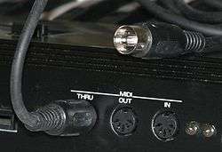
MIDI connectors are standard 5-pin 180° DIN connectors which at one time were a de facto European standard for audio interconnection. Over time the simpler American RCA phono jack has left MIDI as the only place where DIN is commonly encountered in modern equipment. Only two of the five pins (pins 4 and 5) are used for MIDI signal transmission.
Some computers or their sound cards have 15-pin D-subminiature connectors, called game ports, that can be used for MIDI IN/MIDI OUT. The connector supports both MIDI and analog joystick functions. Access to the MIDI signals is provided by a short adapter cable that converts the D-subminiature pinout into DIN connectors. The recommended method of connecting two 5-pin DIN cables to a 15-pin D-subminiature computer port can be found at the MIDI.org web site. The MIDI specification very conservatively states that the maximum distance MIDI can be transmitted is 15 meters (50 feet), but it can normally go much farther.
There exists a USB connection standard and a standard for MIDI over Ethernet and Internet called RTP MIDI being developed by the IETF, available from standard RFC sites.
Most MIDI capable instruments feature a MIDI IN, MIDI OUT, and occasionally a MIDI THRU connection in the form of five-pin DIN connectors. In order to build a two-way physical connection between two devices, a pair of cables must be used. The MIDI THRU jack simply echoes the signal entering the device at MIDI-IN. This makes it possible to control several devices from a single source.
The 1985 Atari ST was the first home computer to sport the original five-pin DIN format, making it a very popular platform for running MIDI sequencer software. Most PC soundcards from the late 1990s had the ability to terminate a MIDI connection, usually through a MIDI IN/MIDI OUT converter on the game port. The game port has been supplanted in the modern PC by USB devices, and so typically a PC owner will need to purchase a MIDI interface that attaches to the USB or FireWire port of their machine to use MIDI. Most current digital audio interfaces are equipped with MIDI ports.
Message format
Every MIDI connection is a one-way connection from the MIDI Out connector of the sending device to the MIDI In connector of the receiving device. Each such connection can carry a stream of MIDI messages, with most messages representing a common musical performance event or gesture such as note-on, note-off, controller value change (including volume, pedal, modulation signals, etc.), pitch bend, program change, aftertouch, channel pressure. All of those messages include channel number. There are 16 possible channels in the protocol. The channels are used to separate "voices" or "instruments", somewhat like tracks in a multi-track mixer.
The ability to multiplex 16 "channels" onto a single wire makes it possible to control several instruments at once using a single MIDI connection. When a MIDI instrument is capable of producing several independent sounds or "voices" simultaneously (a multitimbral instrument), MIDI channels are used to address these sections independently. (This should not be confused with "polyphonic"; the ability to play several notes simultaneously in the same "voice".)
In more detail, MIDI 1.0 defines several basic message types of channel messages:
- Note messages can represent any note from '''C (i.e. five octaves below middle C or 8.176 Hz in common Western musical tuning; designated as MIDI note 0) to g (i.e. five octaves above the G above middle C or 12,544 Hz; designated as MIDI note 127) with precision down to the semitone. A note-on message starts a note, and a separate note-off message is needed to end it. If running status is 'active', a note-on message with the velocity byte set to zero is used in place of a note-off message.
- Pitch-bend messages range in ±2 semitones (sometimes adjustable with Registered Parameter Numbers), with precision of 1/8192 semitone (The human ear cannot hear the difference between adjacent pure tones that differ by less than 1/20 semitone). Most synthesizers allow you to adjust the pitch bend range over several octaves.
- "Control Change" messages (frequently wrongly called Continuous Controller) are quite versatile; they are usually generated by a musician using knobs, sliders, footswitches, or pressure on a physical MIDI controller (or MIDI-equipped instrument). While the response to these messages is generally totally up to the receiving device, they are typically used to change the tone, timbre, or volume of an instrument's sound. In non-musical applications of MIDI, Control Change messages can be used to move motorized faders, to dim lights, or even to move a motorized joint in an animatronic figure.
- Program change messages are sent to an instrument on a particular channel to instruct it to recall another patch, or program. The MIDI protocol uses 7 bits for this message, supporting only 128 programs to change to. Many devices which are more modern than the MIDI specification store far more than 128 programs. To overcome the limitation, a bank-switching method has been added to the spec (Each bank of 128 programs can be selected using two controller messages for MSB and LSB, enabling access to 16,384 banks of 128 programs, or a total of 2,097,152 programs).
- Aftertouch messages (also known as Poly Pressure messages) are sent in some instruments to indicate pressure changes on the note while it is being played. Similarly, channel pressure changes the pressure for the entire instrument, not just one note. The channel pressure messages are more commonly implemented in most synthesizers, while the individual pressure sensors that aftertouch messages require are reserved mainly for expensive, high-end synthesizers.
In addition to the channel-based messages, there are system-related messages not addressed to any particular channel. These include:
- Manufacturer's System Exclusive messages (also known as Manufacturer SysEx, Manuf Sysx, etc.) are defined by the manufacturer of the sequencer/synthesizer and can be any length. These messages are commonly used to send non-MIDI data over a MIDI connection, such as patch settings, a sound sample, or a sequencer's memory dump. Because they are defined by the device's manufacturer, they are mainly used for backup purposes and rarely (if ever) useful in another MIDI device.
- Real Time System Exclusive messages include the significant MIDI Show Control extension which enables all types of entertainment equipment to easily communicate with each other through the process of show control.
- System messages contain meta-data about other MIDI messages. A sequencer, for example, often sends MIDI clock messages during playback that correspond to the MIDI timecode, so the device receiving the messages (usually a synthesizer) will be able to keep time. Also, some devices will send Active Sense messages, used only to keep the connection between the sender and the receiver alive after all MIDI communication has ceased.
MIDI can be used to provide facilities for playing in musical tunings different from the 12 tone per octave, equal-tempered tuning used in most western musical traditions. However, apart from using pitch-bend to control each note, these features have not been implemented by all instrument manufacturers.
Low bandwidth
MIDI messages are extremely compact, due to the low bandwidth of the connection (this is due to adoption of a fixed baud rate of 31250 baud in the standard[3]), and the need for real-time accuracy. Most messages consist of a status byte (channel number in the low 4 bits, and an opcode in the high 4 bits), followed by one or two data bytes. However, the serial nature of MIDI messages means that long strings of MIDI messages take an appreciable time to send, at times even causing audible delays, especially when dealing with dense musical information or when many channels are particularly active.
To further optimize the data stream, "Running status", a convention that allows the status byte to be omitted if it would be the same as that of the previous message, helps to mitigate bandwidth issues somewhat.
See also
- MIDI Machine Control
- MIDI Show Control
- MIDI timecode
- MIDI controller
- MIDI mockup
- MIDI usage and applications
- MIDI Tuning Standard
- MIDI beat clock
- Midiboard
- General MIDI
- Comparison of MIDI standards
References
- ↑ MIDI Manufacturers Association
- ↑ Association of Musical Electronics Industry
- ↑ Dr. Sebastian Anthony Birch The MIDI Physical Layer