Loudspeaker enclosure
A loudspeaker enclosure or loudspeaker cabinet is an enclosure (often box-shaped) in which speaker drivers (e.g., loudspeakers and tweeters) and associated electronic hardware, such as crossover circuits and, in some cases, power amplifiers, are mounted. Enclosures may range in design from simple, homemade DIY rectangular particle-board boxes to very complex, expensive computer-designed hi-fi cabinets that incorporate composite materials, internal baffles, horns, ports and acoustic insulation. Loudspeaker enclosures range in size from small "bookshelf" speaker cabinets with 4" woofers and small tweeters designed for listening to music with a hi-fi system in a private home to huge, heavy subwoofer enclosures with multiple 18" or even 21" speakers designed for use in stadium concert sound reinforcement systems for rock music concerts.
The primary role of the enclosure is to prevent sound waves generated by the rearward-facing surface of the diaphragm of an open speaker driver interacting with sound waves generated at the front of the speaker driver. Because the forward- and rearward-generated sounds are out of phase with each other, any interaction between the two in the listening space creates a distortion of the original signal as it was intended to be reproduced. As such, a loudspeaker cannot be used without installing it in a cabinet of some type, or mounting it into a wall or ceiling. Additionally, because the sound waves would travel different paths through the listening space, the sound waves in an unmounted speaker would arrive at the listener's position at slightly different times, introducing echo and reverberation effects not part of the original sound.
The enclosure also plays a role in managing vibration induced by the driver frame and moving airmass within the enclosure, as well as heat generated by driver voice coils and amplifiers (especially where woofers and subwoofers are concerned). Sometimes considered part of the enclosure, the base, may include specially designed "feet" to decouple the speaker from the floor. Enclosures designed for use in PA systems, sound reinforcement systems and for use by instrument players (e.g., bass amp cabinets have a number of features to make them easier to transport, such as carrying handles on the top or sides, metal or plastic corner protectors, and metal grilles to protect the speakers. Speaker enclosures designed for use in a home or recording studio typically do not have handles or corner protectors, although they do still usually have a cloth or mesh cover to protect the woofer.
Speaker enclosures are used in homes in stereo systems, home cinema systems, televisions, boom boxes and many other audio appliances. Small speaker enclosures are used in car stereo systems. Speaker cabinets are key components of a number of commercial applications, including sound reinforcement systems, movie theatre sound systems and recording studios. Electric musical instruments invented in the 20th century, such as the electric guitar, electric bass and synthesizer, among others, are amplified using instrument amplifiers and speaker cabinets (e.g., guitar amplifiers).
History
Early on, radio loudspeakers consisted of horns, often sold separately from the radio itself, (typically a small wood box containing the radio's electronic circuits[1]), so they were not usually housed in an enclosure.[2] When paper cone loudspeaker drivers were introduced in the mid 1920s, radio cabinets began to be made larger to enclose both the electronics and the loudspeaker.[3] These cabinets were made largely for the sake of appearance, with the loudspeaker simply mounted behind a round hole in the cabinet. It was observed that the enclosure had a strong effect on the bass response of the speaker. Since the rear of the loudspeaker radiates sound out of phase from the front, there can be constructive and destructive interference for loudspeakers without enclosures, and below frequencies related to the baffle dimensions in open-baffled loudspeakers (described in Background section, below). This results in a loss of bass and comb filtering (i.e. response peaks and dips in power regardless of the signal meant to be reproduced).
Before the 1950s many manufacturers did not fully enclose their loudspeaker cabinets; the back of the cabinet was typically left open. This was done for several reasons, not least because electronics (at that time tube equipment) could be placed inside and cooled by convection in the open enclosure.
Most of the enclosure types discussed in this article were invented either to wall off the out of phase sound from one side of the driver, or to modify it so that it could be used to enhance the sound produced from the other side. However, a few designs have ventured in a different direction, attempting to incorporate the natural acoustic properties of the cabinet material rather than deaden it, and shape the cabinet so that the rear can remain open and still provide good bass response with limited comb filtering.[4]
Background
In some respects, the ideal mounting for a low-frequency loudspeaker driver would be a rigid flat panel of infinite size with infinite space behind it. This would entirely prevent the rear sound waves from interfering (i.e., comb filter cancellations) with the sound waves from the front. An "open baffle" loudspeaker is an approximation of this, since the driver is mounted on a panel, with dimensions comparable to the lowest wavelength to be reproduced. In either case, the driver would need a relatively stiff suspension to provide the restoring force which might have been provided at low frequencies by a smaller sealed or ported enclosure, so few drivers are suitable for this kind of mounting.
The forward- and rearward-generated sounds of a speaker driver appear out of phase from each other because they are generated through opposite motion of the diaphragm and because they travel different paths before converging at the listener's position. A speaker driver mounted on a finite baffle will display a physical phenomenon known as interference which can result in a perceivable frequency-dependent sound attenuation. This phenomenon is particularly noticeable at low frequencies where the wavelengths are large enough that interference will affect the entire listening area.
Since infinite baffles are impractical and finite baffles tend to suffer poor response as wavelengths approach the dimensions of the baffle (i.e. at lower frequencies), most loudspeaker cabinets use some sort of structure (usually a box) to contain the out of phase sound energy. The box is typically made of wood, wood composite, or more recently plastic, for reasons of ease of construction and appearance. Stone, concrete, plaster, and even building structures have also been used.
Enclosures can have a significant effect beyond what was intended, with panel resonances, diffraction from cabinet edges and standing wave energy from internal reflection/reinforcement modes being among the possible problems. Bothersome resonances can be reduced by increasing enclosure mass or rigidity, by increasing the damping of enclosure walls or wall/surface treatment combinations, by adding stiff cross bracing, or by adding internal absorption. Wharfedale, in some designs, reduced panel resonance by using two wooden cabinets (one inside the other) with the space between filled with sand. Home experimenters have even designed speakers built from concrete, granite[5] and other exotic materials for similar reasons.
Many diffraction problems, above the lower frequencies, can be alleviated by the shape of the enclosure, such as by avoiding sharp corners on the front of the enclosure. Research experiments from the 1930s by Dr. Harry F. Olson showed that curved loudspeaker baffles reduce some response deviations due to sound wave diffraction. It was discovered later that careful placement of a speaker on a sharp-edged baffle can reduce diffraction-caused response problems. Sometimes the differences in phase response at frequencies shared by different drivers can be addressed by adjusting the vertical location of the smaller drivers (usually backwards), or by leaning or 'stepping' the front baffle, so that the wavefront from all drivers is coherent at and around the crossover frequencies in the speaker's normal sound field. The acoustic center of the driver dictates the amount of rearward offset needed to "time-align" the drivers.
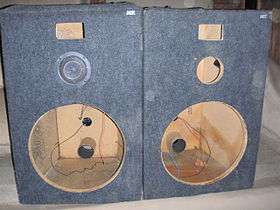
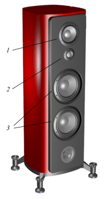
Types
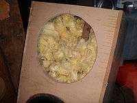
.jpg)
Enclosures used for woofers and subwoofers can be adequately modeled in the low-frequency region (approximately 100–200 Hz and below) using acoustics and the lumped component models. Electrical filter theory has been used with considerable success for some enclosure types. For the purposes of this type of analysis, each enclosure must be classified according to a specific topology. The designer must balance low bass extension, linear frequency response, efficiency, distortion, loudness and enclosure size, while simultaneously addressing issues higher in the audible frequency range such as diffraction from enclosure edges, the baffle step effect when wavelengths approach enclosure dimensions, crossovers, and driver blending.
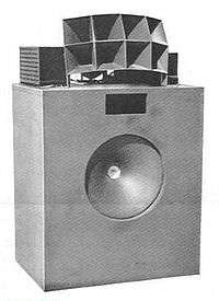
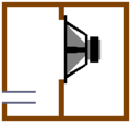
Sealed (or closed) enclosures
.png)
The loudspeaker driver's moving mass and compliance (slackness or reciprocal stiffness of the suspension) determines the driver's resonant frequency (Fs). In combination with the damping properties of the system (both mechanical and electrical) all these factors affect the low-frequency response of sealed-box systems. Output falls below the system's resonant frequency (Fc), defined as the frequency of peak impedance. In a closed-box, the air inside the box acts as a spring, returning the cone to the 'zero' position in the absence of a signal. A significant increase in the effective volume of a sealed-box loudspeaker can be achieved by a filling of fibrous material, typically fiberglass, bonded acetate fiber (BAF) or long-fiber wool. The effective volume increase can be as much as 40% and is due primarily to a reduction in the speed of sound propagation through the filler material as compared to air.[6] The enclosure or driver must have a small leak so internal and external pressures can equalise over time, to compensate for barometric pressure or altitude; the porous nature of paper cones, or an imperfectly sealed enclosure, is normally sufficient to provide this slow pressure equalisation.
Infinite baffle
A variation on the 'open baffle' approach is to mount the loudspeaker driver in a very large sealed enclosure, providing minimal 'air spring' restoring force to the cone. This minimizes the change in the driver's resonant frequency caused by the enclosure. Some infinite baffle 'enclosures' have used an adjoining room, basement, or a closet or attic. This is often the case with exotic rotary woofer installations, as they are intended to go to frequencies lower than 20 Hertz and displace large volumes of air. "Infinite baffle" or simply "IB" is also used as a generic term for sealed enclosures of any size, the name being used because of the ability of a sealed enclosure to prevent any interaction between the forward and rear radiation of a driver at low frequencies.
In conceptual terms an infinite baffle is a flat baffle that extends out to infinity – the so-called “endless plate”. A genuine infinite baffle cannot be constructed but a very large baffle such as the wall of a room can be considered to be a practical equivalent. A genuine infinite-baffle loudspeaker has an infinite volume (a half-space) on each side of the baffle and has no baffle step. However the term “infinite-baffle loudspeaker” can fairly be applied to any loudspeaker that behaves (or closely approximates) in all respects as if the drive unit is mounted in a genuine infinite baffle. The term is often and erroneously used of sealed enclosures which cannot exhibit infinite-baffle behavior unless their internal volume is much greater than the Vas Thiele/Small of the drive unit AND the front baffle dimensions are ideally several wavelengths of the lowest output frequency. It is important to distinguish between genuine infinite-baffle topology and so-called infinite-baffle or IB “enclosures” which may not meet genuine infinite-baffle criteria. The distinction becomes important when interpreting textbook usage of the term.[7][8]
Acoustic suspension
Acoustic suspension or air suspension is a variation of the closed-box enclosure, using a box size that exploits the almost linear air spring which results. The "spring" suspension that restores the cone to a neutral position is a combination of an exceptionally compliant (soft) woofer suspension, and the air inside the enclosure. At frequencies below system resonance, the air pressure caused by the cone motion is the dominant force. Developed by Edgar Villchur in 1954, this technique was used in the very successful Acoustic Research line of "bookshelf" speakers in the 1960s-70s. The acoustic suspension principle takes advantage of this relatively linear spring. The enhanced suspension linearity of this type of system is an advantage. A disadvantage is lower efficiency compared to vented enclosures.
Isobaric loading
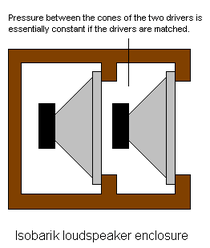
The isobaric loudspeaker configuration was first introduced by Harry F. Olson in the early 1950s, and refers to systems in which two or more identical woofers (bass drivers) operate simultaneously, with a common body of enclosed air adjoining one side of each diaphragm. In practical applications, they are most often used to improve low-end frequency response without increasing cabinet size, though at the expense of cost and weight. Two identical, loudspeakers are coupled to work together as one unit: they are mounted one behind the other in a casing to define a chamber of air in between. The volume of this "isobaric" chamber is usually chosen to be fairly small for reasons of convenience. The two drivers operating in tandem exhibit exactly the same behavior as one loudspeaker in twice the cabinet.
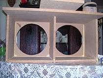
Ported (or reflex) enclosures
Bass-reflex
.png)
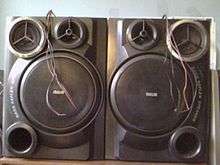
Also known as vented (or ported) systems, these enclosures have a vent or hole cut into the cabinet and a port tube affixed to the hold, to improve low-frequency output, increase efficiency, or reduce the size of an enclosure. Bass reflex designs are used in home stereo speakers (including both low- to mid-priced speaker cabinets and expensive hi-fi cabinets), bass amplifier speaker cabinets, keyboard amplifier cabinets, subwoofer cabinets and PA system speaker cabinets. Vented or ported cabinets use cabinet openings or transform and transmit low-frequency energy from the rear of the speaker to the listener. They deliberately and successfully exploit the principles of the Helmholtz resonator. As with sealed enclosures, they may be empty, lined, filled or (rarely) stuffed with damping materials. Port tuning frequency is a function of cross-section and length. This enclosure type is very common, and provides more sound pressure level near the tuning frequency than a sealed enclosure of the same volume, though it actually has less low frequency extension since the "rolloff" is steeper (24db/oct vs. 12db/oct for a sealed enclosure). Malcolm Hill pioneered the use of these designs in a live event context in the early 1970s.[9]
Vented system design using computer modeling has been practiced since about 1985, when researchers Thiele and Small first systematically applied electrical filter theory to the acoustic behavior of loudspeakers in enclosures. While ported loudspeakers had been produced for many years before computer modeling, achieving optimum performance was challenging, as it is a complex sum of the properties of the specific driver, the enclosure and port, because of imperfect understanding of the assorted interactions. These enclosures are sensitive to small variations in driver characteristics and require special quality control concern for uniform performance across a production run. Bass ports are widely used in subwoofers for PA systems and sound reinforcement systems, in bass amp speaker cabinets and in keyboard amp speaker cabinets.
Passive radiator
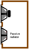
A passive radiator speaker uses a second "passive" driver, or drone, to produce similar low-frequency extension, or efficiency increase, or enclosure size reduction, similar to ported enclosures. The passive driver is not wired to an amplifier; instead, it moves in response to changing enclosure pressures. In theory, such designs are variations of the bass reflex type, but with the advantage of avoiding a relatively small port or tube through which air moves, sometimes noisily. Tuning adjustments for a passive radiator are usually accomplished more quickly than with a bass reflex design since such corrections can be as simple as mass adjustments to the drone. The disadvantages are that a passive radiator requires precision construction quite like a driver, thus increasing costs, and has excursion limitations.
Compound or band-pass
A 4th order electrical bandpass filter can be simulated by a vented box in which the contribution from the rear face of the driver cone is trapped in a sealed box, and the radiation from the front surface of the cone is into a ported chamber. This modifies the resonance of the driver. In its simplest form a compound enclosure has two chambers. The dividing wall between the chambers holds the driver; typically only one chamber is ported.
If the enclosure on each side of the woofer has a port in it then the enclosure yields a 6th order band-pass response. These are considerably harder to design and tend to be very sensitive to driver characteristics. As in other reflex enclosures, the ports may generally be replaced by passive radiators if desired. An eighth order bandpass box is another variation which also has a narrow frequency range. They are often used to achieve sound pressure levels in which case a bass tone of a specific frequency would be used versus anything musical. They are complicated to build and must be done quite precisely in order to perform nearly as intended.[10]
Aperiodic enclosures
This design falls between acoustic suspension and bass reflex enclosures. It can be thought of as either a leaky sealed box or a ported box with large amounts of port damping. By setting up a port, and then blocking it precisely with sufficiently tightly packed fiber filling, it's possible to adjust the damping in the port as desired. The result is control of the resonance behavior of the system which improves low-frequency reproduction, according to some designers (and driver manufacturers). Dynaco was a primary producer of these enclosures for many years, using designs developed by a Scandinavian driver maker. The design remains uncommon among commercial designs currently available. A reason for this may be that adding damping material is a needlessly inefficient method of increasing damping; the same alignment can be achieved by simply choosing a loudspeaker driver with the appropriate parameters and precisely tuning the enclosure and port for the desired response.
A similar technique has been used in aftermarket car audio; it is called "aperiodic membrane" (AP). A resistive mat is placed in front of or directly behind the loudspeaker driver (usually mounted on the rear deck of the car in order to use the trunk as an enclosure). The loudspeaker driver is sealed to the mat so that all acoustic output in one direction must pass through the mat. This increases mechanical damping, and the resulting decrease in the impedance magnitude at resonance is generally the desired effect, though there is no perceived or objective benefit to this. Again, this technique reduces efficiency and the same result can be achieved through selection of a driver with a lower Q factor, or even via electronic equalization. This is reinforced by the purveyors of AP membranes; they are often sold with an electronic processor which, via equalization, restores the bass output lost through the mechanical damping. The effect of the equalization is opposite to that of the AP membrane, resulting in a loss of damping and an effective response similar to that of the loudspeaker without the aperiodic membrane and electronic processor.
Dipole enclosures
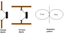
A dipole enclosure in its simplest form is a driver located on a flat baffle panel, similar to older open back cabinet designs. The baffle's edges are sometimes folded back to reduce its apparent size, creating a sort of open-backed box. A rectangular cross-section is more common than curved ones since it is easier to fabricate in a folded form than a circular one. The baffle dimensions are typically chosen to obtain a particular low-frequency response, with larger dimensions giving a lower frequency before the front and rear waves interfere with each other. A dipole enclosure has a "figure-of-eight" radiation pattern, which means that there is a reduction in sound pressure, or loudness, at the sides as compared to the front and rear. This is useful if it can be used to prevent the sound from being as loud in some places as in others.
Horn enclosures
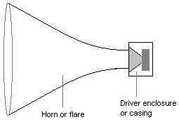
A horn loudspeaker is a speaker system using a horn to match the driver cone to the air. The horn structure itself does not amplify, but rather improves the coupling between the speaker driver and the air. Properly designed horns have the effect of making the speaker cone transfer more of the electrical energy in the voice coil into the air; in effect the driver appears to have higher efficiency. Horns can help control dispersion at higher frequencies which is useful in some applications such as sound reinforcement. The mathematical theory of horn coupling is well developed and understood, though implementation is sometimes difficult. Properly designed horns for high frequencies are small (above say 3 kHz or so, a few centimetres or inches), those for mid-range frequencies (perhaps 300 Hz to 2 kHz) much larger, perhaps 30 to 60 cm (1 or 2 feet), and for low frequencies (under 300 Hz) very large, a few metres (dozens of feet). In the 1950s, a few high fidelity enthusiasts actually built full sized horns whose structures were built into a house wall or basement. With the coming of stereo (two speakers) and surround sound (four or more), plain horns became even more impractical. Various speaker manufacturers have produced folded low-frequency horns which are much smaller (e.g., Altec Lansing, JBL, Klipsch, Lowther, Tannoy) and actually fit in practical rooms. These are necessarily compromises, and because they are physically complex, they are expensive.
Multiple entry horn
The multiple entry horn (also known as a coentrant horn, unity horn or synergy horn) uses several different drivers mounted on the horn at stepped distances from the horn's apex, where the high frequency driver is placed. Depending on implementation, this design offers an improvement in transient response as each of the drivers is aligned in phase and time and exits the same horn mouth. A more uniform radiation pattern throughout the frequency range is also possible.[11] A uniform pattern allows smooth arraying of multiple enclosures.[12]
Tapped horn
Both sides of a long-excursion high-power driver in a tapped horn enclosure are ported into the horn itself, with one path length long and the other short. These two paths combine in phase at the horn's mouth within the frequency range of interest. This design is especially effective at subwoofer frequencies and offers reductions in enclosure size along with more output.[12]
Transmission line
A perfect transmission line enclosure has an infinitely long line, stuffed with absorbent material such that all the rear radiation of the driver is fully absorbed, down to the lowest frequencies. Theoretically, the vent at the far end could be closed or open with no difference in performance. The density of and material used for the stuffing is critical, as too much stuffing will cause reflections due to back-pressure, whilst insufficient stuffing will allow sound to pass through to the vent. Stuffing often is of different materials and densities, changing as one gets further from the back of the driver's diaphragm.
Consequent to the above, practical Transmission Line loudspeakers are not true Transmission Lines, as there is generally output from the vent at the lowest frequencies. They can be thought of as a waveguide in which the structure shifts the phase of the driver's rear output by at least 90°, thereby reinforcing the frequencies near the driver's Fs. Transmission lines tend to be larger than ported enclosures of approximately comparable performance, due to the size and length of the guide required (typically 1/4 the longest wavelength of interest).
The design is often described as non-resonant, and some designs are sufficiently stuffed with absorbent material that there is indeed not much output from the line's port. But it is the inherent resonance (typically at 1/4 wavelength) that can enhance the bass response in this type of enclosure, albeit with less absorbent stuffing. Among the first examples of this enclosure design approach were the projects published in Wireless World by Bailey in the early 1970s, and the commercial designs of the now defunct IMF Electronics which received critical acclaim at about the same time.
A variation on the transmission line enclosure uses a tapered tube, with the terminus (opening/port) having a smaller area than the throat. The tapering tube can be coiled for lower frequency driver enclosures to reduce the dimensions of the speaker system, resulting in a seashell like appearance. Bose uses similar patented technology on their Wave and Acoustic Waveguide music systems.[13]
Numerical simulations by George L. Augspurger and Martin J. King have helped refine the theory and practical design of these systems.[14][15]
Quarter wave enclosure
A quarter Wave resonator is a transmission line tuned to form a standing quarter wave at a frequency somewhat below the driver´s frequency FS. When properly designed, a port that is of much smaller diameter than the main pipe located at the end of the pipe then produces the driver´s backward radiation in phase with the speaker driver itself; greatly adding to the bass output. Such designs tend to be less dominant in certain bass frequencies than the more common bass reflex designs and followers of such designs claim an advantage in clarity of the bass with a better congruency of the fundamental frequencies to the overtones.[16]
Some loudspeaker designers like Martin J. King and Bjørn Johannessen consider the term "quarter wave enclosure" as a more fitting term for most transmission lines and since acoustically, quarter wavelengths produce standing waves inside the enclosure that are used to produce the bass response emanating from the port. These designs can be considered a mass-loaded transmission line design or a bass reflex design, as well as a quarter wave enclosure.[17] Quarter wave resonators have seen a revival as commercial applications with the onset of neodymium drivers that enable this design to produce relatively low bass extensions within a relatively small speaker enclosure.[16]
Tapered quarter-wave pipe
The tapered quarter-wave pipe (TQWP) is an example of a combination of transmission line and horn effects. It is highly regarded by some speaker designers. The concept is that the sound emitted from the rear of the loudspeaker driver is progressively reflected and absorbed along the length of the tapering tube, almost completely preventing internally reflected sound being retransmitted through the cone of the loudspeaker. The lower part of the pipe acts as a horn while the top can be visualised as an extended compression chamber. The entire pipe can also be seen as a tapered transmission line in inverted form. (A traditional tapered transmission line, confusingly also sometimes referred to as a TQWP, has a smaller mouth area than throat area.) Its relatively low adoption in commercial speakers can mostly be attributed to the large resulting dimensions of the speaker produced and the expense of manufacturing a rigid tapering tube. The TQWP is also known as a Voigt pipe and was introduced in 1934 by Paul G. A. H. Voigt, Lowther's original driver designer.
See also
- Audio crossover
- Full-range speaker
- Tweeter
- Super tweeter
- Midrange speaker
- Woofer
- Subwoofer
- Acoustic transmission line
- Guitar speaker cabinet
- Powered speakers
- Soundbar
- Speaker grille
Notes
- ↑ Illustrations Retrieved November 26, 2012.
- ↑ Illustrations , Retrieved November 26, 2012.
- ↑ Illustrations Retrieved November 26, 2012.
- ↑ Auditorium 23 , Retrieved November 26, 2012.
- ↑ DIY Granite Speaker Project
- ↑ L. Beranek, Acoustics, 2nd Ed. 1986.
- ↑ Acoustics, Leo Beranek, 1954 Ed (P118, 1996 print)
- ↑ eg. The Art of Sound Reproduction, John Watkinson, 2004
- ↑ Hill heritage and design philosophy
- ↑ http://www.the12volt.com/caraudio/boxes6.asp#2
- ↑ Loudspeaker Profile: Danley Sound Labs SH-50 Live Sound International. May 2006, Volume 15, Number 5. TechTopic. Pat Brown.
- 1 2 Danley Sound Labs. A White Paper on Danley Sound Labs Tapped Horn and Synergy Horn Technologies
- ↑ http://www.bose.com/controller?event=VIEW_STATIC_PAGE_EVENT&url=/learning/waveguide.jsp
- ↑ Loudspeakers on Damped Pipes. AES E-Library: Augspurger, George L. JAES Volume 48, Issue 5, pp. 424-436. May 2000
- ↑ Quarter Wavelength Loudspeaker Design by Martin J. King. July 17, 2002 (last revised February 25, 2008)
- 1 2 http://www.kvart-bolge.com/#!concept/c1w4l
- ↑ http://www.quarter-wave.com
External links
- How a Hole-in-the-Box Works - information about bass reflex.
- Quarter-Wave - details about transmission line design
- Humble Homemade Hifi - DIY site with examples & plans of several speaker enclosure types
- Free Speaker Plans - Community oriented DIY loudspeaker design plans, general resources and forum.