Log-periodic antenna
| Part of a series on |
| Antennas |
|---|
 |
|
Common types |
|
Radiation sources / regions |
A log-periodic antenna (LP), also known as a log-periodic array or log-periodic aerial, is a multi-element, directional, antenna designed to operate over a wide band of frequencies. It was invented by Dwight Isbell and Raymond DuHamel at the University of Illinois in 1958.
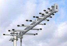
The most common form of log-periodic antenna is the log-periodic dipole array or LPDA, The LPDA consists of a number of half-wave dipole driven elements of gradually increasing length, each consisting of a pair of metal rods. The dipoles are mounted close together in a line, connected in parallel to the feedline with alternating phase. Electrically, it simulates a series of two or three-element Yagi antennas connected together, each set tuned to a different frequency.
LPDA antennas look somewhat similar to Yagi antennas, in that they both consist of dipole rod elements mounted in a line along a support boom, but they work in very different ways. Adding elements to a Yagi increases its directionality, or gain, while adding elements to a LPDA increases its frequency response, or bandwidth.
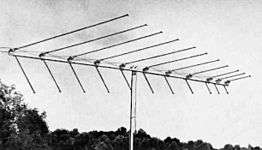
One large application for LPDAs is in rooftop terrestrial television antennas, since they must have large bandwidth to cover the wide television bands of roughly 54–88 and 174–216 MHz in the VHF and 470–890 MHz in the UHF while also having high gain for adequate fringe reception. One widely used design for television reception combined a Yagi for UHF reception in front of a larger LPDA for VHF.
Basic concept
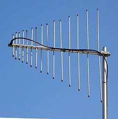
The LPDA normally consists of a series of dipoles known as "elements" positioned along a support boom lying along the antenna axis. The elements are spaced at intervals following a logarithmic function of the frequency, known as d or sigma. The length of the elements correspond to resonance at different frequencies within the antenna's overall bandwidth. This leads to a series of ever-shorter dipoles towards the "front" of the antenna. The relationship between the lengths is a function known as tau. The ever-decreasing lengths makes the LPDA look, when viewed from the top, like a triangle or arrow with the tip pointed in the direction of the peak radiation pattern. Sigma and tau are the key design elements of the LPDA design.[1][2]
Every element in the LPDA design is "active", that is, connected electrically to the feedline along with the other elements, though at any one frequency most of the elements draw little current from it. Each successive element is connected in opposite phase to the active connection running as a transmission line along the boom. For that reason, that transmission line can often be seen zig-zagging across the support boom holding the elements.[2] One common design ploy is to use two booms that also acts as the transmission line, mounting the dipoles on the alternate booms. Other forms of the log-periodic design replace the dipoles with the transmission line itself, forming the log-periodic zig-zag antenna.[3] Many other forms using the transmission wire as the active element also exist.[4]
The Yagi and the LPDA designs look very similar at first glance, as both consist of a number of dipole elements spaced out along a support boom. The Yagi, however, has only a single dipole connected to the transmission line, usually the second one from the back of the array. The other dipoles on the boom are passive elements, with their two sides shorted, acting as directors or reflectors depending on their slightly different lengths and position relative to the driven element. The difference between the LPDA and Yagi becomes obvious when examining their electrical connections; Yagi's lack the zig-zag connection between the elements. Another clear difference is the length of the dipoles; LPDA designs have much shorter dipoles towards the front of the antenna, forming a triangular shape as seen from the top, whereas the difference in lengths of Yagi elements is less noticeable or non-existent. Another visible difference is the spacing between the elements, which is normally constant in the Yagi, but becomes exponentially wider along the LPDA. Although both directional, the LPDA is intended to achieve a very wide bandwidth, whereas the Yagi has a very narrow bandwidth but achieves greater gain.
In general terms, the log-periodic design operates somewhat similar to a series of three-element Yagis, where each set of three consecutive elements forms a separate antenna with the driven element in the center, a director in front and reflector behind. However, the system is somewhat more complex than that, and all the elements contribute to some degree, so the gain for any given frequency is higher than a Yagi of the same dimensions as any one section of the log-periodic. However, it should also be noted that a Yagi with the same number of elements as a log-periodic would have far higher gain, as all of those elements are improving the gain of a single driven element. In its common use as a television antenna, it was common to combine a log-periodic design for VHF with a Yagi for UHF, with both halves being roughly equal in size. This resulted in much higher gain for UHF, typically on the order of 10 to 14 dB on the Yagi side and 6.5 dB for the log-periodic.[5] But this extra gain was needed anyway in order to make up for a number of problems with UHF signals.
It should be strictly noted that the log-periodic shape, according to the IEEE definition,[6] does not provide with broadband property for antennas.[7][8] The broadband property of log-periodic antennas comes from its self-complementarity. Y. Mushiake found, for what he termed "the simplest self-complementary planar antenna," a driving point impedance of η0/2=188.4 Ω at frequencies well within its bandwidth limits.[9][10][11]


History
The log periodic antenna was invented by Dwight E. Isbell, Raymond DuHamel and variants by Paul Mayes. The University of Illinois at Urbana-Champaign had patented the Isbell and Mayes-Carrel antennas and licensed the design as a package exclusively to JFD electronics in New York. Channel Master and Blonder-Tongue ignored the patents and produced a wide range of antennas based on this design. Lawsuits regarding the antenna patent which the UI Foundation lost, evolved into the Blonder-Tongue Doctrine.[12] This precedent governs patent litigation.[13]
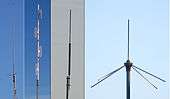
Short wave broadcast antennas
.JPG)
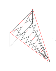
The log periodic is commonly used in high power short wave broadcasting[14] where it is desired to invest in only a single antenna to cover transmissions over multiple bands. The log-periodic zig-zag design with up to 16 zig zag sections has been used. These large antennas are typically designed to cover 6 to 26 MHz but even larger ones have been built which operate as low as 2 MHz. Power ratings are available up to 500 kW. The antenna is fed from the small end. The antenna shown here would have about 14 dBi gain. An antenna array consisting of two such antennas, one above the other and driven in phase has a gain of up to 17 dBi. Being log-periodic, the antenna's main characteristics (radiation pattern, gain, driving point impedance) are almost constant over its entire frequency range, with the match to a 300 Ω feed line achieving a standing wave ratio of better than 2:1 over that range.
References
- ↑ The Log-Periodic Dipole Array"
- 1 2 Log Periodic Dipole Array (LPDA)
- ↑ "Log-periodic zig zag antenna", US Patent 3355740
- ↑ Photo Archive Of Antennas, Illinois Historic Archive
- ↑ Davidson, David (2010). Computational Electromagnetics for RF and Microwave Engineering. Cambridge University Press. p. 178.
- ↑ “Log-periodic antenna Any one of a class of antennas having a structural geometry such that its impedance and radiation characteristics repeat periodically as the logarithm of frequency.” (see Acknowledgments, and footnote in page 1), Self-Complementary Antennas―Principle of Self-Complementarity for Constant Impedance―, by Y. Mushiake, Springer-Verlag London Ltd., London, 1996
- ↑ Y. Mushiake, “Constant-impedance antennas," ’’J. IECE Japan’’, 48, 4, pp. 580-584, April 1965. (in Japanese)
- ↑ "Y. Mushiake, ' Log-periodic structure provides no broad-band property for antennas."' J. IEE Japan, 69, 3, p. 88, March 1949.". Sm.rim.or.jp. Retrieved 15 January 2014.
- ↑ "Y. Mushiake, 'Origination of self-complementary structure and discovery of its constant-impedance property.' J. IEE Japan, 69, 3, p. 88, March 1949. (in Japanese)". Sm.rim.or.jp. Retrieved 31 January 2014.
- ↑ "Y. Mushiake, ' Infinite freedom."'". Sm.rim.or.jp. Retrieved 15 January 2014.
- ↑ V. H. Rumsey, ‘’Frequency independent antennas’’, Academic Press, New York and London. 1966. [p. 55]
- ↑ http://definitions.uslegal.com/b/blonder-tongue-doctrine/
- ↑ http://www.ece.illinois.edu/mediacenter/alumninews/alumninews-sum04a.pdf
- ↑ http://www.antenna.be/art1.html
Notes
![]() This article incorporates public domain material from the General Services Administration document "Federal Standard 1037C" (in support of MIL-STD-188).
This article incorporates public domain material from the General Services Administration document "Federal Standard 1037C" (in support of MIL-STD-188).
See also
External links
- Antenna-Theory.com Log-Periodic Tooth Antenna Page
- Blonder-Tongue Doctrine
- LPDA Online Calculation
- Some thoughts on Log-Periodic Antennas
- Com-Power Corporation - Log Periodic Antennas for EMC testing