Linear induction motor
A linear induction motor (LIM) is an alternating current (AC), asynchronous linear motor that works by the same general principles as other induction motors but is typically designed to directly produce motion in a straight line. Characteristically, linear induction motors have a finite primary or secondary length, which generates end-effects, whereas a conventional induction motor is arranged in an endless loop.
Despite their name, not all linear induction motors produce linear motion; some linear induction motors are employed for generating rotations of large diameters where the use of a continuous primary would be very expensive.
As with rotary motors, linear motors frequently run on a three-phase power supply and can support very high speeds. However, there are end-effects that reduce the motor's force, and it is often not possible to fit a gearbox to trade off force and speed. Linear induction motors are thus frequently less energy efficient than normal rotary motors for any given required force output.
LIMs, unlike their rotary counterparts, can give a levitation effect. They are therefore often used where contactless force is required, where low maintenance is desirable, or where the duty cycle is low. Their practical uses include magnetic levitation, linear propulsion, and linear actuators. They have also been used for pumping liquid metals.[1]
History
The history of linear electric motors can be traced back at least as far as the 1840s to the work of Charles Wheatstone at King's College in London,[2] but Wheatstone's model was too inefficient to be practical. A feasible linear induction motor is described in US patent 782312 (1905; inventor Alfred Zehden of Frankfurt-am-Main), and is for driving trains or lifts. German engineer Hermann Kemper built a working model in 1935.[3] In the late 1940s, professor Eric Laithwaite of Imperial College in London developed the first full-size working model.

In a single-sided version, the magnetic field can create repulsion forces that push the conductor away from the stator, levitating it and carrying it along the direction of the moving magnetic field. Laithwaite called the later versions a magnetic river. These versions of the linear induction motor use a principle called transverse flux where two opposite poles are placed side by side. This permits very long poles to be used, and thus permits high speed and efficiency.[4]
Construction
A linear electric motor's primary typically consists of a flat magnetic core (generally laminated) with transverse slots that are often straight cut[5] with coils laid into the slots, with each phase giving an alternating polarity so that the different phases physically overlap.
The secondary is frequently a sheet of aluminium, often with an iron backing plate. Some LIMs are double sided with one primary on each side of the secondary, and, in this case, no iron backing is needed.
Two types of linear motor exist: a short primary, where the coils are truncated shorter than the secondary, and a short secondary, where the conductive plate is smaller. Short secondary LIMs are often wound as parallel connections between coils of the same phase, whereas short primaries are usually wound in series.[6]
The primaries of transverse flux LIMs have a series of twin poles lying transversely side-by-side with opposite winding directions. These poles are typically made either with a suitably cut laminated backing plate or a series of transverse U-cores.
Principles
In this electric motor design, the force is produced by a linearly moving magnetic field acting on conductors in the field. Any conductor, be it a loop, a coil, or simply a piece of plate metal, that is placed in this field will have eddy currents induced in it thus creating an opposing magnetic field in accordance with Lenz's law. The two opposing fields will repel each other, creating motion as the magnetic field sweeps through the metal.

where is supply frequency in Hz, p is the number of poles, and is the synchronous speed of the magnetic field in revolutions per second.


The travelling field pattern has a velocity of:

where is velocity of the linear travelling field in m/s, and t is the pole pitch.

For a slip of s, the speed of the secondary in a linear motor is given by

Forces
Thrust
The drive generated by linear induction motors is somewhat similar to conventional induction motors; the drive forces show a roughly similar characteristic shape relative to slip, albeit modulated by end effects.[8]
End effect
Unlike a circular induction motor, a linear induction motor shows 'end effects'. These end effects include losses in performance and efficiency that are believed to be caused by magnetic energy being carried away and lost at the end of the primary by the relative movement of the primary and secondary.
With a short secondary, the behaviour is almost identical to a rotary machine, provided it is at least two poles long but with a short primary reduction in thrust that occurs at low slip (below about 0.3) until it is eight poles or longer.[6]
However, because of end effects, linear motors cannot 'run light' -- normal induction motors are able to run the motor with a near synchronous field under low load conditions. In contrast, end effects create much more significant losses with linear motors.[6]
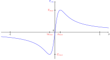
Levitation
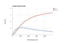
In addition, unlike a rotary motor, an electrodynamic levitation force is shown, this is zero at zero slip, and gives a roughly constant amount of force/gap as slip increases in either direction. This occurs in single sided motors, and levitation will not usually occur when an iron backing plate is used on the secondary, since this causes an attraction that overwhelms the lifting force.[8]
Performance
Linear induction motors are often less efficient than conventional rotary induction motors; the end effects and the relatively large air gap that is often present will typically reduce the forces produced for the same electrical power. The larger air gap also increases the inductance of the motor which can require larger and more expensive capacitors.
However conversely, linear induction motors can avoid the need for gearboxes and similar drivetrains, and these have their own losses; and working knowledge of the importance of the goodness factor can minimise the effects of the larger air gap. In any case power use is not always the most important consideration. For example, in many cases linear induction motors have far fewer moving parts, and have very low maintenance.
Uses

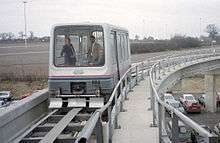
Because of these properties, linear motors are often used in maglev propulsion, as in the Japanese Linimo magnetic levitation train line near Nagoya.
The world's first commercial automated maglev system was a low-speed maglev shuttle that ran from the airport terminal of Birmingham International Airport to the nearby Birmingham International railway station between 1984–1995.[9] The length of the track was 600 metres (2,000 ft), and trains "flew" at an altitude of 15 millimetres (0.59 in), levitated by electromagnets, and propelled with linear induction motors.[10] It was in operation for nearly eleven years, but obsolescence problems with the electronic systems made it unreliable in its later years. One of the original cars is now on display at Railworld in Peterborough, together with the RTV31 hover train vehicle.
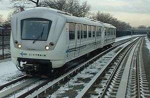
However, linear motors have been used independently of magnetic levitation, as in Bombardier's Advanced Rapid Transit systems worldwide and a number of modern Japanese subways, including Tokyo's Toei Oedo Line.
Linear induction motor technology is also used in some roller coasters. At present it is still impractical on street running trams, although this, in theory, could be done by burying it in a slotted conduit.
Outside of public transportation, vertical linear motors have been proposed as lifting mechanisms in deep mines, and the use of linear motors is growing in motion control applications. They are also often used on sliding doors, such as those of low floor trams such as the Citadis and the Eurotram. Dual axis linear motors also exist. These specialized devices have been used to provide direct X-Y motion for precision laser cutting of cloth and sheet metal, automated drafting, and cable forming. Most linear motors in use are LIM (linear induction motors) or LSM (linear synchronous motors). Linear DC motors are not used as it includes more cost and linear SRM suffers from poor thrust. So for long run in traction LIM is mostly preferred and for short run LSM is mostly preferred.

Linear induction motors have also been used for launching aircraft, the Westinghouse Electropult[6] system in 1945 was an early example and the Electromagnetic Aircraft Launch System (EMALS) was due to be delivered in 2010.
Linear induction motors are also used in looms, magnetic levitation enable bobbins to float between the fibers without direct contact.
See also
References
- ↑ Einstein Linear induction motor
- ↑ "Charles Wheatstone - College History - King's College London". Kcl.ac.uk. Archived from the original on October 21, 2009. Retrieved 2010-03-01.
- ↑ http://cem.colorado.edu/archives/fl1997/thor.html
- ↑ Patent number 3585423, 1971 Laithwaite et al
- ↑ http://www.manchesteruniversitypress.co.uk/uploads/docs/380117.pdf
- 1 2 3 4 linear Electric Machines- A Personal View ERIC R. LAITHWAITE, FELLOW, IEEE, PROCEEDINGS OF THE IEEE, VOL. 63, NO. 2, FEBRUARY 1975
- 1 2 3 http://electrical.sunilsaharan.in/2010/07/linear-induction-motor-working.html
- 1 2 Force Analysis of Linear Induction Motor for Magnetic Levitation System 14th International Power Electronics and Motion Control Conference, EPE-PEMC 2010
- ↑ "The magnetic attraction of trains". BBC News. 9 November 1999.
- ↑ Maglev, A film for The People Mover Group