Isometric projection
| Part of a series on |
| Graphical projection |
|---|
 |
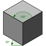
Isometric projection is a method for visually representing three-dimensional objects in two dimensions in technical and engineering drawings. It is an axonometric projection in which the three coordinate axes appear equally foreshortened and the angle between any two of them is 120 degrees.
Overview
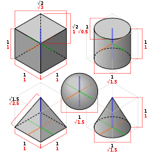
The term "isometric" comes from the Greek for "equal measure", reflecting that the scale along each axis of the projection is the same (unlike some other forms of graphical projection).
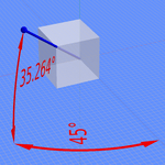
An isometric view of an object can be obtained by choosing the viewing direction such that the angles between the projections of the x, y, and z axes are all the same, or 120°. For example, with a cube, this is done by first looking straight towards one face. Next, the cube is rotated ±45° about the vertical axis, followed by a rotation of approximately ±35.264° (precisely arcsin 1⁄√3 or arctan 1⁄√2, which is related to the Magic angle) about the horizontal axis. Note that with the cube (see image) the perimeter of the resulting 2D drawing is a perfect regular hexagon: all the black lines have equal length and all the cube's faces are the same area. Isometric graph paper can be placed under a normal piece of drawing paper to help achieve the effect without calculation.
In a similar way, an isometric view can be obtained in a 3D scene. Starting with the camera aligned parallel to the floor and aligned to the coordinate axes, it is first rotated vertically (around the horizontal axis) by about 35.264° as above, then ±45° around the vertical axis.
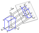
Another way isometric projection can be visualized is by considering a view within a cubical room starting in an upper corner and looking towards the opposite, lower corner. The x-axis extends diagonally down and right, the y-axis extends diagonally down and left, and the z-axis is straight up. Depth is also shown by height on the image. Lines drawn along the axes are at 120° to one another.
The term "isometric" is often mistakenly used to refer to axonometric projections generally. (There are three types of axonometric projections: isometric, dimetric and trimetric.)
Rotation angles
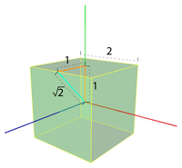
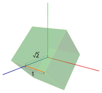
From the two angles needed for an isometric projection, the value of the second may seem counterintuitive and deserves some further explanation. Let’s first imagine a cube with sides of length 2, and its center positioned at the axis origin. We can calculate the length of the line from its center to the middle of any edge as √2 using Pythagoras' theorem . By rotating the cube by 45° on the x-axis, the point (1, 1, 1) will therefore become (1, 0, √2) as depicted in the diagram. The second rotation aims to bring the same point on the positive z-axis and so needs to perform a rotation of value equal to the arctangent of 1⁄√2 which is approximately 35.264°.
Mathematics
There are eight different orientations to obtain an isometric view, depending into which octant the viewer looks. The isometric transform from a point ax,y,z in 3D space to a point bx,y in 2D space looking into the first octant can be written mathematically with rotation matrices as:

where α = arcsin(tan 30°) ≈ 35.264° and β = 45°. As explained above, this is a rotation around the vertical (here y) axis by β, followed by a rotation around the horizontal (here x) axis by α. This is then followed by an orthographic projection to the xy-plane:

The other 7 possibilities are obtained by either rotating to the opposite sides or not, and then inverting the view direction or not.[1]
History and limitations
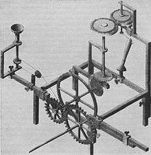
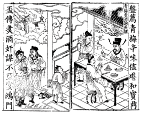
First formalized by Professor William Farish (1759–1837), the concept of isometry had existed in a rough empirical form for centuries.[3][4] From the middle of the 19th century, isometry became an "invaluable tool for engineers, and soon thereafter axonometry and isometry were incorporated in the curriculum of architectural training courses in Europe and the U.S."[5] According to Jan Krikke (2000)[6] however, "axonometry originated in China. Its function in Chinese art was similar to linear perspective in European art. Axonometry, and the pictorial grammar that goes with it, has taken on a new significance with the advent of visual computing".[6]
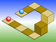
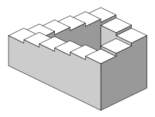
As with all types of parallel projection, objects drawn with isometric projection do not appear larger or smaller as they extend closer to or away from the viewer. While advantageous for architectural drawings where measurements need to be taken directly, the result is a perceived distortion, as unlike perspective projection, it is not how our eyes or photography normally work. It also can easily result in situations where depth and altitude are difficult to gauge, as is shown in the illustration to the right. This can appear to create paradoxical or impossible shapes, such as the Penrose stairs.
Usage in video games and pixel art
Isometric graphics were used in early video games during the 80s and 90s, as the technique provided a limited 3D effect that could be achieved with the constrained resources of microcomputers of the era.
The style was also used for sprites and pixel art, achieving a characteristic style still used in retrogaming.
See also
References
- ↑ Ingrid Carlbom; Joseph Paciorek; Dan Lim (December 1978). "Planar Geometric Projections and Viewing Transformations". ACM Computing Surveys. ACM. 10 (4): 465–502. doi:10.1145/356744.356750.
- ↑ William Farish (1822) "On Isometrical Perspective". In: Cambridge Philosophical Transactions. 1 (1822).
- ↑ Barclay G. Jones (1986). Protecting historic architecture and museum collections from natural disasters. University of Michigan. ISBN 0-409-90035-4. p.243.
- ↑ Charles Edmund Moorhouse (1974). Visual messages: graphic communication for senior students.
- ↑ J. Krikke (1996). "A Chinese perspective for cyberspace?". In: International Institute for Asian Studies Newsletter, 9, Summer 1996.
- 1 2 Jan Krikke (2000). "Axonometry: a matter of perspective". In: Computer Graphics and Applications, IEEE Jul/Aug 2000. Vol 20 (4), pp. 7–11.
External links
| Wikimedia Commons has media related to Isometric projection. |