Inlet cone
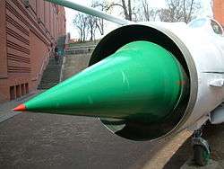
Inlet cones (sometimes called shock cones or inlet centerbodies[1]) are a component of some supersonic aircraft and missiles. They are primarily used on ramjets, such as the D-21 Tagboard and Lockheed X-7. Some turbojet aircraft including the Su-7, MiG-21, English Electric Lightning, and SR-71 also use an inlet cone.
Purpose
The main purpose of an inlet cone is to slow the flow of air from supersonic flight speed to a subsonic speed before it enters the engine. Except for scramjet engines, all airbreathing jet engines need subsonic airflow to operate properly, and require a diffuser to prevent supersonic airflow inside the engine. At supersonic flight speeds a conical shock wave, sloping rearwards, forms at the apex of the cone. Air passing through the conical shock wave (and subsequent reflections) slows to a low supersonic speed. The air then passes through a strong normal shock wave, within the diffuser passage, and exits at a subsonic velocity. The resulting intake system is more efficient (in terms of pressure recovery) than the much simpler pitot intake.
Shape
The inlet cone is shaped so that the shock wave that forms on its apex is directed to the lip of the intake; this allows the intake to operate properly in supersonic flight. As speed increases, the shock wave becomes increasingly more oblique (the cone gets narrower). For higher flight speeds inlet cones are designed to move axially to control how the capture area varies with the duct internal throat area. For best intake operation this required area ratio gets bigger with increasing flight Mach number, hence the large inlet cone movement on the SR-71 which had to perform well from zero to Mach 3.2.
Operation
At subsonic flight speeds, the conical inlet operates much like a pitot intake or subsonic diffuser. However, as the vehicle goes supersonic a conical shock wave appears, emanating from the cone apex. The flow area through the shock wave decreases and the air is compressed. As the flight Mach number increases, the conical shock wave becomes more oblique and eventually impinges on the intake lip.
For higher flight speeds a moving cone becomes necessary to allow the supersonic compression to occur more efficiently over a wider range of speeds. With increasing flight speed the cone is moved to the rear, or into the intake. Due to the shape of the cone surface and the internal duct surface the internal flow area gets less as required to continue compressing the air supersonically. The compression occurring in this path is called "internal compression" (as opposed to the "external compression" on the cone). At the minimum flow area, or throat, a normal or plane shock occurs. The flow area then increases for subsonic compression, or diffusion, up to the engine face.
The position of the cone within the intake is usually controlled automatically to keep the plane shock wave correctly located just downstream of the throat. Certain circumstances can cause the shock wave to be expelled from the intake. This is known as an unstart.
The boundary layer on the cone is stretched as it moves up the cone preventing flow separation, but for the internal compression and the subsonic compression the boundary layer still tends to separate and usually is sucked through tiny holes in the wall. As a side note on the aerospike engine the boundary layer gets thicker towards the end of the cone as needed for the greater speed difference between the air molecules just on the surface of the cone and the fully accelerated stream of air.
Alternative shapes
Some air inlets feature a biconic centrebody (MIG-21) to form two conic shock waves, both focused on the lip of the intake. This improves pressure recovery. Some aircraft (F-104, Mirage III) use a semi-conic centrebody. The F-111 has a quarter cone, which moves axially, followed by an expanding cone section.
Concorde, F-15 Eagle, MiG-25 Foxbat, and the A-5 Vigilante use so-called 2D inlets, where the nacelle is rectangular and a flat intake ramp replaces the dual cones. Inlet ramps allow for swept inlet cowls (F-22 Raptor, F-35 Lightning II) to avoid shocks.
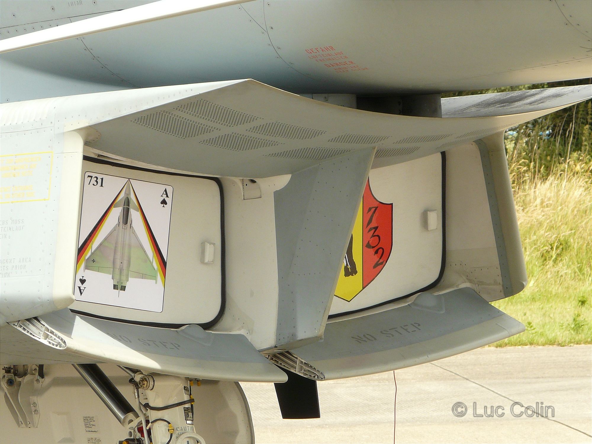
Some other supersonic aircraft (Eurofighter Typhoon) use a variable lower cowl lip[2] for high angle of attack operation and a bleed system (porous wall) incorporated on the intake ramp to facilitate stabilization of the shock system at supersonic Mach numbers. For the improvement of the intake flow (reduced distortion), air is dumped via an intake bleed slot on the ramp side downstream of the intake. The ramp, which is separated from the fuselage by a diverter, produces an oblique shock in order to decelerate the flow. The leading edge of the splitter plate separating the two intakes is located downstream of this oblique shock.[3]
At least one supersonic and one subsonic ramp is used, but for improved seal multiple supersonic ramps can be used. The boundary layer (something which the subsonic pitot inlet avoids by external compression) tends to separate and the smaller boundary layer of the ramp inlet is an advantage compared to the inlet cone. To avoid separation vortex generators are used, which mix the boundary layer with the free flow (or the boundary layer is sucked away through a porous surface, leading to drag). After the fan the hot slow intermixed air is passed by the engine, while the fast cold air is delivered to the engine.
After the engine the comparatively cold bypass air is used as an isolation between the engine exhaust and the walls. Again two ramps can be used to form a variable supersonic nozzle. Often a mirror-symmetric set-up is used with ramps on top and on the bottom.
There is one possibility for a stable, shockless supersonic to subsonic transition. This is used in transonic wings and would ultimately mean to send the air into a loop, forming a vortex. Then the final shock to subsonic speed is oblique with the subsonic region moving from the outside of the vortex to the inside.
Many supersonic aircraft (F-16 Fighting Falcon) dispense with the conical centrebody and employ a simple pitot intake. A detached, strong normal shock appears directly in front of the inlet at supersonic flight speeds, which leads to poor pressure recovery.
Also NASA adds a gap through the whole compressor. Supersonic flow jumps over it by means of ramps, while subsonic flow is able to turn and exit through the gap. In this way a stall is easier to remove . Also there are plans to measure the air in front of the inlet to detect turbulence and adjust the inlet in real-time.
Ramjet
As the compression of the inlet rises with speed the compression of the first compressor stage is reduced accordingly. The afterburner behind a turbine runs with a stoichiometric mixture like a ramjet but at higher pressure and thus more efficiency than a pure ramjet. It is claimed that an inlet at Mach 3.5 produces the same compression (44:1 ) as the whole compressor of a jet engine at zero speed, so the turbine should be bypassed then.
List of engines using an inlet cone
 F-104 fixed cone
 X-35 fixed cone Diverterless supersonic inlet
 Movable cone of Su-20
 On the SR-71 the cone moves backwards at higher Mach number
 The Mirage III also has a half cone
See also
References
- Benson, T. (2004). High Speed Aerodynamics Index. Retrieved Nov. 19, 2004.
- Eden, P. & Moeng, S. (2002). Modern Military Aircraft Anatomy. Aerospace Publishing Ltd. ISBN 1-58663-684-7.
External links
![]() Media related to Inlet cones at Wikimedia Commons
Media related to Inlet cones at Wikimedia Commons