Image stitching
Image stitching or photo stitching is the process of combining multiple photographic images with overlapping fields of view to produce a segmented panorama or high-resolution image. Commonly performed through the use of computer software, most approaches to image stitching require nearly exact overlaps between images and identical exposures to produce seamless results,[1][2] although some stitching algorithms actually benefit from differently exposed images by doing HDR (High Dynamic Range) imaging in regions of overlap.[3][4] Some digital cameras can stitch their photos internally. Image stitching is widely used in today’s world in applications such as
- “Image Stabilization” feature in camcorders which use frame-rate image alignment.
- High resolution photo mosaics in digital maps and satellite photos.
- Medical Imaging.
- Multiple image super-resolution.
- Video Stitching.[5]
- Object Insertion.
Process stages

The image stitching process can be divided into three main components - image registration, calibration and blending.
- Possible issues with image stitching
Since the illumination in two views cannot be guaranteed to be the same stitching two images could create a visible seam. Other reasons for the seam appearing could be the background changing between two images for the same continuous foreground.
In general the major issues to deal with are presence of parallax, lens distortion, scene motion, and exposure differences.
For panoramic stitching the ideal set of images will have a reasonable amount of overlap (at least 15 – 30%) to overcome lens distortion and have enough detectable features. The set of images will have consistent exposure between frames to minimize the probability of seams occurring.
But in the non ideal real life case the intensity varies across the whole scene and so does the contrast and intensity across the frames. Lens distortion, motion in the scene and misalignment all cause ghosting.
Also the ratio of width to height of panorama image needs to be taken into account to create a visually pleasing composite.
- General overview of image stitching algorithms
- Firstly algorithms are needed to determine the appropriate mathematical model relating pixel coordinates in one image to pixel coordinates in another. This is for image alignment.
- Next, we need to estimate the correct alignments relating various pairs (or collections) of images. Algorithms that combine direct pixel-to-pixel comparisons with gradient descent (and other optimization techniques) can be used to estimate these parameters.
- Distinctive features can be found in each image and then efficiently matched to rapidly establish correspondences between pairs of images. When multiple images exist in a panorama, techniques have been developed to compute a globally consistent set of alignments and to efficiently discover which images overlap one another.
- For image stitching, we must first decide on a final compositing surface onto which to warp or projectively transform and place all of the aligned images. We also need to develop algorithms to seamlessly blend the overlapping images, even in the presence of parallax, lens distortion, scene motion, and exposure differences.
- Keypoint detection
Feature detection is necessary to automatically find correspondences between images. Robust correspondences are required in order to estimate the necessary transformation to align an image with the image it is being composted on. Corners, blobs, harris corners and Difference of gaussian of harris corners (DoG) are good features since they are repeatable and distinct. One of the first operators for interest point detection was developed by Hans P. Moravec in 1977 for his research involving the automatic navigation of a robot through a clustered environment. It was also Moravec who defined the concept of "points of interest" in an image and concluded these interest points could be used to find matching regions in different images. The Moravec operator is considered to be a corner detector because it defines interest points as points where there are large intensity variations in all directions. This often is the case at corners. It is interesting to note, however, that Moravec was not specifically interested in finding corners, just distinct regions in an image that could be used to register consecutive image frames. Harris and Stephens improved upon Moravec's corner detector by considering the differential of the corner score with respect to direction directly. They needed it as a processing step to build interpretations of a robot's environment based on image sequences. Like Moravec, they needed a method to match corresponding points in consecutive image frames, but were interested in tracking both corners and edges between frames. SIFT and SURF are recent keypoint or interest point detector algorithms but a point to note is that these are patented and their commercial usage restricted. Once a feature has been detected then a descriptor method like SIFT descriptor can be applied to later match them.
Registration
Image registration involves matching features[6] in a set of images or using direct alignment methods to search for image alignments that minimize the sum of absolute differences between overlapping pixels.[7] When using direct alignment methods one might first calibrate one's images to get better results. Additionally, users may input a rough model of the panorama to help the feature matching stage, so that - for example - only neighboring images are searched for matching features. Since there are smaller group of features for matching, the result of the search is more accurate and execution of the comparison is faster.
To estimate a robust model from the data, a common method used is known as RANSAC.
The name RANSAC is an abbreviation for "RANdom SAmple Consensus". It is an iterative method for robust parameter estimation to fit mathematical models from sets of observed data points which may contain outliers. The algorithm is non-deterministic in the sense that it produces a reasonable result only with a certain probability, with this probability increasing as more iterations are performed. It being a probabilistic method means that different results will be obtained for every time the algorithm is run.
The RANSAC algorithm has found many applications in computer vision, including the simultaneous solving of the correspondence problem and the estimation of the fundamental matrix related to a pair of stereo cameras.
The basic assumption of the method is that the data consists of "inliers", i.e., data whose distribution can be explained by some mathematical model, and "outliers" which are data that do not fit the model. Outliers are considered points which come from noise, erroneous measurements, or simply incorrect data.
For the problem of homography estimation, RANSAC works by trying to fit several models using some of the point pairs and then checking if the models were able to relate most of the points. The best model, i.e., the homography which produces the highest number of correct matches, is then chosen as the answer for the problem thus if the ratio of number of outliers to data points is very low the RANSAC outputs a decent model fitting the data.
Calibration
Image calibration aims to minimize differences between an ideal lens models and the camera-lens combination that was used, optical defects such as distortions, exposure differences between images, vignetting,[8] camera response and chromatic aberrations. If feature detection methods were used to register images and absolute positions of the features were recorded and saved, stitching software may use the data for geometric optimization of the images in addition to placing the images on the panosphere. Panotools and its various derivative programs use this method.
- Alignment
Alignment may be necessary to transform an image to match the view point of the image it is being composted with. Alignment in simple terms is a change in the coordinates system so that it adopts a new coordinate system which outputs image matching the required viewpoint. The types of transformations an image may go through are pure translation, pure rotation, a similarity transform which includes translation, rotation and scaling of the image which needs to be transformed, Affine or projective transform. Projective transformation is the farthest an image can transform ( in the set of two dimensional planar transformations ) where only visible features that are preserved in the transformed image are straight lines whereas parallelism is maintained in an affine transform. Projective transformation can be mathematically described as x’ = H * x Where x is points in the old coordinate system, x’ is the corresponding points in the transformed image and H is the homography matrix. Expressing the points x and x’ using the camera intrinsics (K and K’) and its rotation and translation to the real world coordinates X and X’ we get x = K * [R t] * X and x’ = K’ * [R’ t’] * X’ using the above two equations and the homography relation between x’ and x we can derive H = K’ * R’ R-1 * K-1 The homography matrix H has 8 parameters or degrees of freedom. The homography can be computed using Direct Linear Transform and Singular value decomposition where A * h = 0 Where A is the matrix constructed using the coordinates of correspondences and h is the one dimensional vector of the 9 elements of the reshaped homography matrix. To get to h we can simple apply SVD A = U * S * VT And h = V (column corresponding to the smallest singular vector). This is true since h lies in the null space of A. Since we have 8 degrees of freedom the algorithm requires at least four point correspondences. In case when RANSAC is used to estimate the homography and multiple correspondences are available the correct homography matrix is the one with the maximum number of inliers. Composting Composting is the process where the rectified images are aligned in such a way that they appear as a single shot of a scene. Composting can be automatically since the algorithm now knows which correspondences overlap.
Blending
Image blending involves executing the adjustments figured out in the calibration stage, combined with remapping of the images to an output projection. Colors are adjusted between images to compensate for exposure differences. If applicable, high dynamic range merging is done along with motion compensation and deghosting. Images are blended together and seam line adjustment is done to minimize the visibility of seams between images.
The seam can be reduced by a simple gain adjustment. This compensation is basically minimizing intensity difference of overlapping pixels. Image blending algorithm allots more weight to pixels near the center of the image. Gain compensated and multi band blended images compare the best. IJCV 2007. Straightening is another method to rectify the image. Matthew Brown and David G. Lowe in their paper ‘Automatic Panoramic Image Stitching using Invariant Features’ describe methods of straightening which apply a global rotation such that vector u is vertical (in the rendering frame) which effectively removes the wavy effect from output panoramas
Even after gain compensation some image edges are still visible due to a number of unmodelled effects, such as vignetting (intensity decreases towards the edge of the image), parallax effects due to unwanted motion of the optical centre, mis-registration errors due to mismodelling of the camera, radial distortion and so on. Due to these reasons they propose a blending strategy called multi band blending.
Projective layouts

For image segments that have been taken from the same point in space, stitched images can be arranged using one of various map projections.
Rectilinear
Rectilinear projection, where the stitched image is viewed on a two-dimensional plane intersecting the panosphere in a single point. Lines that are straight in reality are shown as straight regardless of their directions on the image. Wide views - around 120° or so - start to exhibit severe distortion near the image borders. One case of rectilinear projection is the use of cube faces with cubic mapping for panorama viewing. Panorama is mapped to six squares, each cube face showing 90 by 90 degree area of the panorama.
Cylindrical
Cylindrical projection, where the stitched image shows a 360° horizontal field of view and a limited vertical field of view. Panoramas in this projection are meant to be viewed as though the image is wrapped into a cylinder and viewed from within. When viewed on a 2D plane, horizontal lines appear curved while vertical lines remain straight.[9] Vertical distortion increases rapidly when nearing the top of the panosphere. There are various other cylindrical formats, such as Mercator and Miller cylindrical which have less distortion near the poles of the panosphere.
Spherical
Spherical projection or equirectangular projection — which is strictly speaking another cylindrical projection — where the stitched image shows a 360° horizontal by 180° vertical field of view i.e. the whole sphere. Panoramas in this projection are meant to be viewed as though the image is wrapped into a sphere and viewed from within. When viewed on a 2D plane, horizontal lines appear curved as in a cylindrical projection, while vertical lines remain vertical.[9]
Panini
Since a panorama is basically a map of a sphere, various other mapping projections from cartographers can also be used if so desired. Additionally there are specialized projections which may have more aesthetically pleasing advantages over normal cartography projections such as Hugin's Panini projection[10] - named after Italian vedutismo painter Giovanni Paolo Pannini[11] - or PTgui's Vedutismo projection.[12] Different projections may be combined in same image for fine tuning the final look of the output image.[13]
Stereographic
Stereographic projection or fisheye projection can be used to form a little planet panorama by pointing the virtual camera straight down and setting the field of view large enough to show the whole ground and some of the areas above it; pointing the virtual camera upwards creates a tunnel effect. Conformality of the stereographic projection may produce more visually pleasing result than equal area fisheye projection as discussed in the stereographic projection's article.
Artifacts
Artifacts due to parallax error
Artifacts due to subject movement
Image-stitching errors
Click to see the whole stitched image
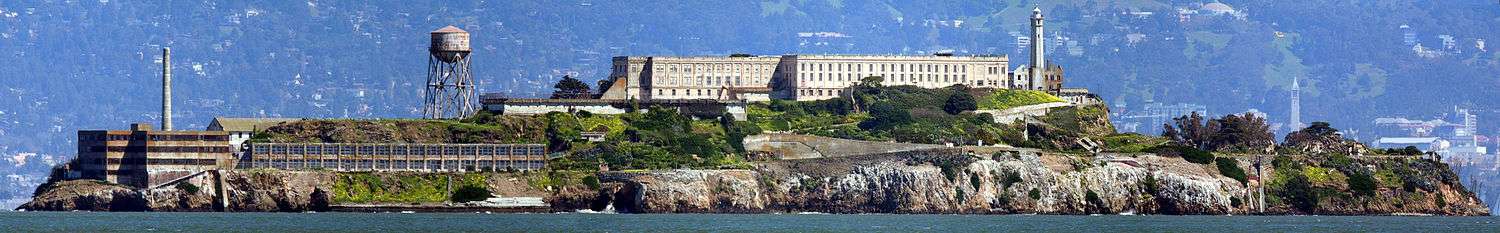
The use of images not taken from the same place (on a pivot about the entrance pupil of the camera)[14] can lead to parallax errors in the final product. When the captured scene features rapid movement or dynamic motion, artifacts may occur as a result of time differences between the image segments. "Blind stitching" through feature-based alignment methods (see autostitch), as opposed to manual selection and stitching, can cause imperfections in the assembly of the panorama. One way to avoid the parallax distortion issue is to make your images for stitching using a large format camera and keeping it stationary during your exposures. If your lens does not move your images will not have parallax issues. There are many sliding adapters on the market that allow for the movement of the capture device (whether a DSLR or medium format digital capture back) without any movement of the camera itself. One such adapter is the Flex Adapter by Phase One. For going above and beyond simple liner stitching on one axis, usually horizontal like the Alcatraz image at the top of this page there is the MultiStitch adapter plate which allows a user to create images that overlap precisely in both the X and Y planes, creating 2-over-2 images for stitching. Another photographic advantage to stitching using a large format camera is that the capture device remains on plane for each and every exposure and rotational imperfections and cylindrical distortions are eliminated.
Software
Dedicated programs include Autostitch, SharpStitch, Kolor Autopano, Hugin, Panorama Maker, Ptgui, Panorama Tools, Microsoft Research Image Composite Editor and CleVR Stitcher. Many other programs can also stitch multiple images; a popular example is Adobe Systems' Photoshop, which includes a tool known as Photomerge and, in the latest versions, the new Auto-Blend. Other programs such as VideoStitch make it possible to stitch videos, and Vahana VR enables real-time video stitching.
See also
- ActionShot panoramic photography
- Anaglyph 3D
- AutoStitch
- Panography
- Panoramic photography
References
- ↑ Steve Mann and R. W. Picard. "Virtual bellows: constructing high-quality images from video.", In Proceedings of the IEEE First International Conference on Image ProcessingAustin, Texas, November 13–16, 1994
- ↑ Ward, Greg (2006). "Hiding seams in high dynamic range panoramas". Proceedings of the 3rd symposium on Applied perception in graphics and visualization. ACM International Conference Proceeding Series. 153. ACM. doi:10.1145/1140491.1140527. ISBN 1-59593-429-4.
- ↑ Steve Mann. "Compositing Multiple Pictures of the Same Scene", Proceedings of the 46th Annual Imaging Science & Technology Conference, May 9–14, Cambridge, Massachusetts, 1993
- ↑ S. Mann, C. Manders, and J. Fung, "The Lightspace Change Constraint Equation (LCCE) with practical application to estimation of the projectivity+gain transformation between multiple pictures of the same subject matter" IEEE International Conference on Acoustics, Speech, and Signal Processing, 6–10 April 2003, pp III - 481-4 vol.3
- ↑ Breszcz, M.; Breckon, T.P. (August 2015). "Real-time Construction and Visualization of Drift-Free Video Mosaics from Unconstrained Camera Motion" (PDF). IET J. Engineering. IET. 2015 (16): 1–12. doi:10.1049/joe.2015.0016. breszcz15mosaic.
- ↑ Szeliski, Richard (2005). "Image Alignment and Stitching" (PDF). Retrieved 2008-06-01.
- ↑ S. Suen; E. Lam; K. Wong (2007). "Photographic stitching with optimized object and color matching based on image derivatives". Optics Express. 15 (12): 7689–7696. doi:10.1364/OE.15.007689. PMID 19547097.
- ↑ Pablo d'Angelo (2007). "Radiometric alignment and vignetting calibration" (PDF).
- 1 2 Wells, Sarah; et al. (2007). "IATH Best Practices Guide to Digital Panoramic Photography". Retrieved 2008-06-01.
- ↑ Hugin.sourceforge.net, hugin manual: Panini
- ↑ Groups.google.com, hugin-ptx mailing list, December 29, 2008
- ↑ PTgui: Projections
- ↑ Tawbaware.com, PTAssembler projections: Hybrid
- ↑ Littlefield, Rik (2006-02-06). "Theory of the "No-Parallax" Point in Panorama Photography" (PDF). ver. 1.0. Retrieved 2008-06-01.
| Wikimedia Commons has media related to Stitching. |