Fused filament fabrication
Fused filament fabrication is a 3D printing process that uses a continuous filament of a thermoplastic material. This is fed from a large coil, through a moving, heated printer extruder head. Molten material is forced out of the print head's nozzle and is deposited on the growing workpiece. The head is moved, under computer control, to define the printed shape. Usually the head moves in layers, moving in two dimensions to deposit one horizontal plane at a time, before moving slightly upwards to begin a new slice. The speed of the extruder head may also be controlled, to stop and start deposition and form an interrupted plane without stringing or dribbling between sections.
Fused filament printing is now the most popular process (by number of machines) for hobbyist-grade 3D printing. As other techniques, such a photpolymerisation and powder sintering, may offer better results at greater cost, they still dominate commercial printing.

The 3D printer head or 3D printer extruder is a part in material extrusion-type printing responsible for raw material melting and forming it into a continuous profile. A wide variety of materials are extruded, including thermoplastics such as acrylonitrile butadiene styrene (ABS), polylactic acid (PLA), high-impact polystyrene (HIPS), thermoplastic polyurethane (TPU), aliphatic polyamides (nylon),[1] and recently also PEEK. [2] Paste-like materials such as ceramics and chocolate can be extruded using the fused filament process and a paste extruder.[3]
Introduction
Additive manufacturing (AM), also referred to as 3D printing, involves manufacturing a part by depositing material layer by-layer. There is a wide array of different AM technologies that can make a part layer-by-layer including material extrusion, binder jetting, material jetting and directed energy deposition.[4]
These process have varied types of extuders and extrude different materials to achieve the final product using layer by layer addition of material approach. The 3D Printer Liquefier is the component predominantly used in Material extrusion type printing.
Extrusion

Extrusion in 3-D printing using material extrusion involves a cold end and a hot end.
The cold end is part of an extruder system that pulls and feed the material from the spool, and pushes it towards the hot end. The cold end is mostly gear- or roller-based supplying torque to the material and controlling the feed rate by means of a stepper motor. By this means the process rate is controlled.
The hot end is the active part which also hosts the liquefier of the 3D printer that melts the filament. It allows the molten plastic to exit from the small nozzle to form a thin and tacky bead of plastic that will adhere to the material it is laid on. the hot end consists of a heating chamber and a nozzle. The hole in the tip (nozzle) has a diameter of between 0.3 mm and 1.0 mm. Different types of nozzles and heating methods are used depending upon the material to be printed.[5]
Some type of 3-D printing machines can have a different type of extrusion system which may not have a heating chamber- the heat is supplied from another source, e.g. a laser.
Extruder mount to rest of machine
The ways extruders are mounted on the rest of the machine have evolved over time into informal mounting standards. These informal standards include:[5]
- the Vertical X Axis Standard,
- the Quick-fit extruder mount,
- the OpenX mount,
etc.
Such de-facto standards allows new extruder designs to be tested on existing printer frames, and new printer frame designs to use existing extruders.
Process

Flow geometry of the extruder, heating method and the melt flow behavior of a non-Newtonian fluid are of main consideration in the part.
A plastic filament is supplied from a reel, either commercially available or home made, and fed into a heated liquefier where it is melted. This melt is then extruded by a nozzle while the incoming filament, still in solid phase, acts as a ‘‘plunger.’’
The nozzle is mounted to a mechanical stage, which can be moved in the xy plane. As the nozzle is moved over the table in a prescribed geometry, it deposits a thin bead of extruded plastic, called a ‘‘road’’ which solidifies quickly upon contact with substrate and/or roads deposited earlier.[6]
Solid layers are generated by following a rasterizing motion where the roads are deposited side by side within an enveloping domain boundary.
Once a layer is completed, the platform is lowered in the z direction in order to start the next layer. This process continues until the fabrication of the object is completed.
For Successful bonding of the roads in the process control of the thermal environment is necessary. Therefore, the system is kept inside a chamber, maintained at a temperature just below the melting point of the material being deposited.
Physics

During extrusion the thermoplastic filament is introduced by mechanical pressure from Rollers, into the liquefier, where it melts and is then extruded. The rollers are the only drive mechanism in the material delivery system, therefore filament is under tensile stress upstream to the roller and under compression at the downstream side acting as a plunger. Therefore compressive stress is the driving force behind the extrusion process.
The force required to extrude the melt must be sufficient to overcome the pressure drop across the system, which strictly depends on the viscous properties of the melted material and the flow geometry of the liquefier and nozzle. The melted material is subjected to shear deformation during the flow. Shear thinning behavior is observed in most of the materials used in this type of 3-D printing. This is modeled using power law for generalized Newtonian fluids.
The temperature is regulated by heat input from electrical coil heaters. The system continuously adjusts the power supplied to the coils according to the temperature difference between the desired value and the value detected by the thermocouple. Forming a Negative Feedback loop. This is similar to Heat Flow rate in Cylindrical Pipe.
Types and uses
| Extruder name | Designer | Mount type | Direct/Bowden | Build Material | Filament Sizes (mm) | Nozzle Sizes (mm) | Maximum Temperature Range | Materials Usesable |
|---|---|---|---|---|---|---|---|---|
| 1730 Full Metal Hotend | Achatz Industries; Kai Parthy | Modified Groove Mount, Round Mount, Heatsink | Both (all-in-one) | All Metal | 1.75 + 3 | 0.25/0.3/0.4/0.6/0.8/1.0 | 300C (max thermistor temp) | Wood, ABS, Nylon, PLA and PET Materials |
| E3D – V6 | Sanjay | Modified Groove Mount | Both | All Metal | 1.75/3 | 0.25/0.3/0.35/0.4/0.6/0.8 | 300C (max thermistor temp) | Wood, ABS, Nylon, PLA and PET Materials |
| J-Head | Brian Reifsnyder | Groove Mount | Direct; Bowden with Adapter | PEEK/PTFE/Metal | 1.75/3 | 0.35/0.45/0.5 | 240C | ABS and PLA Printing |
| Merlin | Srek (Björn Marl) | M10/J-Head Adapter | Both | PEEK/PTFE/Brass | 1.75/3 | 0.2/0.3/0.5 | 240C | Nylon and PLA Printing |
| J-Head Lite V2 | Ohio Plastics | 3/8" Groove Mount | direct (bowden with printed adapter) | PTFE Holder, PTFE Liner, Stainless Steel Barel, Aluminum Heater Block, Brass Nozzle | 1.75 | .4, .35, .3, .25 | 240C | PLA and ABS |
| V3 Hybrid GrooveMount | MakerGear | Groove Mount | direct (bowden with printed adapter) | PEEK, PTFE, stainless steel pins | 1.75/3 | 0.25, 0.35, 0.5 | 200C | PLA and ABS |
| Budaschnozzle | Aleph Objects | Flat Plate | direct (bowden with printed adapter) | PEEK, PTFE, aluminum, wood | 1.75/3 | 0.15 to 0.75 | 240C | Nylon and PLA Printing |
| Pico | B3 innovations | Groove Mount, Groove Mount for Bowden, Flat Plate | Both | stainless steel/brass (all metal) | 1.75/3 | 0.35, 0.4, 0.5, 0.6 | 300C (max thermistor temp) | Multiple |
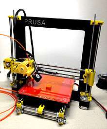
| Prusa Nozzle V2 | Josef Průša | Groove Mount | Both | stainless steel | 3 | – | 300C (max thermistor temp) | PLA and PET materials |
Development
Customer-driven product customization and demand for cost and time savings has increased interest in agility of manufacturing process. This has led to improvements in RP technologies and in particularly of Fused Deposition Modeling.[6] The Development of Extruders is going rapidly because of open source 3-D printer movement caused by products like RepRap. Consistent improvements are seen in the form of increased heating temperature of liquefier, the over-all control and precision of the process and improved support for wide variety of materials to print, including ceramics.
The ways extruders are mounted on the machine has also evolved over time into informal mounting standards. These informal standards include the Vertical X Axis Standard, the Quick-fit extruder mount, the OpenX mount, etc.
Print head kinematics

The majority of fused filament printers follow the same basic design. A flat bed is used as the starting point for the print workpiece. A gantry above this carries the moving print head. The gantry design is optimised for movement mostly in the horizontal X & Y directions, with a slow climb in the Z direction as the piece is printed. Stepper motors drive the movement through either leadscrews or toothed belt drives. It is common, owing to the differences in movement speed, to use toothed belts for the X,Y drives and a leadscrew for Z. Some machines also have X axis movement on the gantry, but move the bed (and print job) for Y. As, unlike laser cutters, head movement speeds are low, stepper motors are universally used and there is no need to use servomotors instead.
Many printers, originally those influenced by the RepRap project, make extensive use of 3D printed components in their own construction. These are typically printed connector blocks with a variety of angled holes, joined by cheap steel threaded rod. This makes a construction that is cheap and easy to assemble, easily allows non-perpendicular framing joints, but does require access to a 3D printer. The notion of 'bootstrapping' 3D printers like this has been something of a dogmatic theme within the RepRap designs. The lack of stiffness in the rod also requires either triangulation, or gives the risk of a gantry structure that flexes and vibrates in service, reducing print quality.
Many machines now use box-like semi-enclosed frames of either laser-cut plywood, plastic or pressed steel sheet. These are cheap, rigid and can also be used as the basis for an enclosed print volume, allowing temperature control within it to control warping of the print job.
A handful of machines use polar coordinates instead, usually machines optimised to print objects with circular symmetry. These have a radial gantry movement and a rotating bed. Although there are some potential mechanical advantages to this design for printing hollow cylinders, their different geometry and the resulting non-mainstream approach to print planning still keeps them from being popular as yet. Although it is an easy task for a robot's motion planning to convert from Cartesian to polar coordinates, gaining any advantage from this design also requires the print slicing algorithms to be aware of the rotational symmetry from the outset.
Rostock printers

A different approach is taken with 'Rostock' pattern printers, based on a delta robot mechanism.[8] These have a large open print volume with a three-armed delta robot mounted at the top. This design of robot is noted for its low inertia and ability for fast movement over a large volume. Stability and freedom from vibration when moving a heavy print head on the end of spindly arms is a technical challenge though. This design has mostly been favoured as a means of gaining a large print volume without a large and heavy gantry.
As the print head moves the distance of its filament from storage coil to head also changes. This tugging on the filament is another technical challenge to overcome, if it is not to affect print quality.
See also
- Ball bearing
- Fused deposition modeling
- Methacrylate
- Plastics extrusion
- Rod
- RAMPS
- Stepper motor
- Spindle
- Thermistor
- Thermocouple
References
- ↑ "RepRap Wiki Category:Thermoplastics". Retrieved 2 November 2014.
- ↑ "3dprint.com, PEEK being 3D-printed". 3dprint.com. March 21, 2015. Retrieved March 26, 2015.
- ↑ "Universal Paste extruder – Ceramic, Food and Real Chocolate 3D Printing". Retrieved 2 November 2014.
- ↑ Brett P. Conner∗, Guha P. Manogharan, Ashley N. Martof, Lauren M. Rodomsky, Caitlyn M. Rodomsky, Dakesha C. Jordan, James W. Limperos; Manogharan; Martof; Rodomsky; Rodomsky; Jordan; Limperos (2014). "Making sense of 3-D printing: Creating a map of additive manufacturing products and services". Addit Manuf. doi:10.1016/j.addma.2014.08.005.
- 1 2 "FDM Extruders". Retrieved 24 October 2014.Reprap extruders
- 1 2 Selc¸uk Gu¨c¸eri, Maurizio Bertoldi; GüçEri; Bertoldi (2014). "Liquefier Dynamics in Fused Deposition". Journal of Manufacturing Science and Engineering. 126 (2): 237. doi:10.1115/1.1688377.Liquefier Dynamics in Fused Deposition
- ↑ "Hot End Reprap". Retrieved 24 October 2014.
- ↑ "Rostock". RepRap.