Horstmann suspension
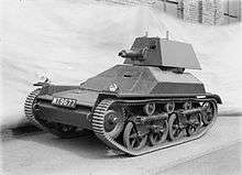
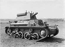
Horstmann suspension is a type of tracked suspension devised by the British engineer Sidney Horstmann in 1922. It was widely used on World War II-era designs, but in the post-war era was increasingly limited to British designs. The last tank to use the design was the Chieftain, from the 1960s.
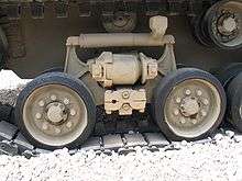
The principle design feature is that two or more wheels are mounted to a common framework. Each wheel is mounted on an L-shaped swing arm that forms a bell crank, so the upward movement of the wheel is turned into sideways motion of the top of the crank. The two arms may be mounted on a common shaft between them, or more commonly, two closely spaced shafts. The two wheels share a common coil spring running horizontally between the tops of the crank arms. This way if one wheel moves up over an obstacle, the spring is compressed against the swing arm of the other wheel.
An advantage to the Horstmann design is that the suspended weight is not placed entirely on the rising wheel, its paired partner will also increase its downward force due to the shared spring, spreading the load. In systems with fully independent wheels, its possible for the entire tank to become suspended on one wheel, which is rare in the Horstmann case. Another advantage is that the spring may work both in compression and expansion, increasing the total travel of the suspension. From a maintenance standpoint, the fact that it connects at a single non-moving point and is otherwise completely self-contained makes it very easy to remove and replace in the field. The location of the spring over the wheels also makes it quite compact, with little or no encroachment on internal hull space.
Mechanically, Horstmann shares much in common with the Christie suspension, which also uses a bell crank and (mostly) horizontal spring. The main difference is that in the Christie each wheel is mounted separately and the spring is usually mounted on or inside the tank hull. The longer spring allows for more controlled flexion and potentially longer throw. However, Christie suspensions are generally more difficult to maintain because the wheels and suspension are mounted separately, and a broken spring can be difficult to reach without removing the wheels first.
Externally, the Horstmann suspension appears similar to the American vertical volute spring suspension (VVSS); both pair the road wheels on a single common mounting. However, the two systems are very different in mechanical terms; the VVSS wheels are mounted on independent pivot points and each has as separate vertical spring. Late World War II American designs replaced VVSS with a version of the Horstmann suspension that replaced its coil springs with the volute springs from the earlier VVSS. This was a major feature of the M4A3E8 model "Easy Eight", so known due to its smooth ride.
The name "Horstmann suspension" may be applied to any transmission system that has two opposed swing arms, no matter what the type of springing between them is.[1] The name also refers to any suspension built by the Horstman company (now Horstman Defence Systems Ltd) whether of the bogie type, torsion beam design, hydrogas, hydropneumatic or other.
The Horstmann system was used on, amongst others, the following vehicles:
Horstman built suspension is used on
- Challenger tank
- Warrior Armoured Fighting Vehicle
- AS-90 self-propelled gun
- TERRIER Engineering Vehicle
- PUMA IFV
References
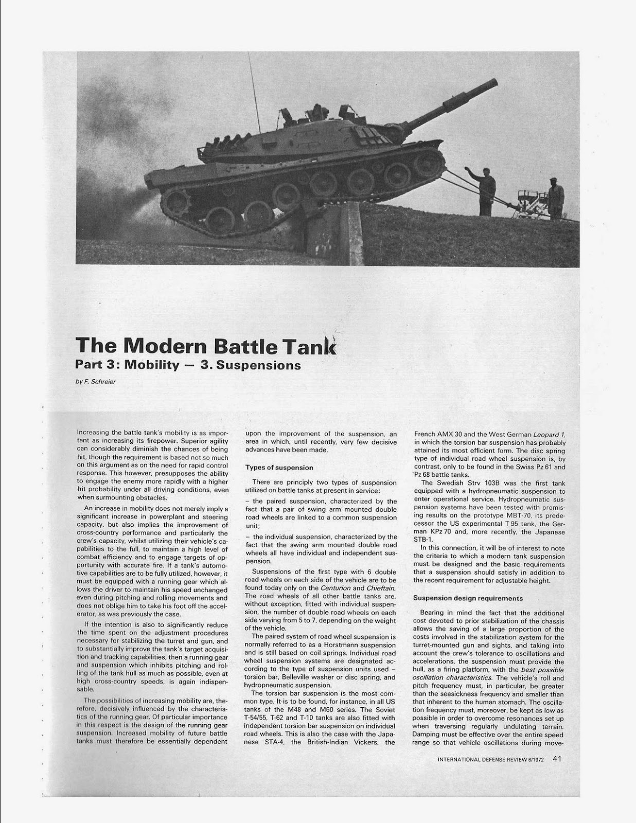
- ↑ Schreier, F. (June 1972). "The Modern Battle Tank Part 3: Mobility, 3: Suspensions". International Defense Review: 41.