Highway Addressable Remote Transducer Protocol
| HART | |
|---|---|
| Protocol Information | |
| Type of Network | Device (Process Automation) |
| Physical Media | 4-20 mA analog instrumentation wiring or 2.4 GHz Wireless |
| Network Topology | One-on-One, multidrop, wireless mesh |
| Maximum Devices | 15 in multidrop |
| Maximum Speed | Depends on physical layer employed |
| Device Addressing | Hardware/software |
| Governing Body | FieldComm Group |
| Website |
www |
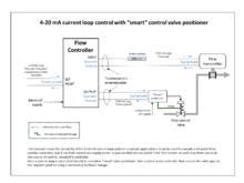
The HART Communication Protocol (Highway Addressable Remote Transducer) is a hybrid analog+digital industrial automation protocol. Its most notable advantage is that it can communicate over legacy 4-20 mA analog instrumentation current loops, sharing the pair of wires used by the analog only host systems.
According to Emerson,[1] due to the huge installed base of 4–20 mA systems throughout the world, the HART Protocol is one of the most popular industrial protocols today. HART protocol has made a good transition protocol for users who wished to use the legacy 4–20 mA signals, but wanted to implement a "smart" protocol.
The protocol was developed by Rosemount Inc., built off the Bell 202 early communications standard in the mid-1980s as a proprietary digital communication protocol for their smart field instruments. Soon it evolved into HART and in 1986 it was made an open protocol. Since then, the capabilities of the protocol have been enhanced by successive revisions to the specification.
Modes
There are two main operational modes of HART instruments: point to point (analog/digital) mode, and multi-drop mode.
Point to point
In point-to-point mode mode the digital signals are overlaid on the 4-20 mA loop current. Both the 4-20 mA current and the digital signal are valid signalling protocols between the controller and measuring instrument or final control element.
The polling address of the instrument is set to "0". Only one instrument can be put on each instrument cable signal pair. One signal, generally specified by the user, is specified to be the 4-20 mA signal. Other signals are sent digitally on top of the 4-20 mA signal. For example, pressure can be sent as 4-20 mA, representing a range of pressures, and temperature can be sent digitally over the same wires. In point-to-point mode, the digital part of the HART protocol can be seen as a kind of digital current loop interface.
Multi-drop
In Multi-drop mode the analog loop current is fixed at 4 mA and it is possible to have more than one instrument on a signal loop.
HART revisions 3 through 5 allowed polling addresses of the instruments to be in the range 1–15. HART revision 6 and later allowed address up to 63. Each instrument needs to have a unique address.
Packet structure
The HART Packet has the following structure:
| Field Name | Length (in bytes) | Purpose |
|---|---|---|
| Preamble | 5–20 | Synchronization and Carrier Detect |
| Start byte | 1 | Specifies Master Number |
| Address | 1-5 | Specifies slave, Specifies Master and Indicates Burst Mode |
| Expansion | 0-3 | This field is 0–3 bytes long and its length is indicated in the Delimiter |
| Command | 1 | Numerical Value for the command to be executed |
| Number of data bytes | 1 | Indicates the size of the Data Field |
| Data | 0–255 | Data associated with the command. BACK and ACK must contain at least two data bytes. |
| Checksum | 1 | XOR of all bytes from Start Byte to Last Byte of Data |
Preamble
Currently all the newer devices implement five byte preamble, since anything greater reduces the communication speed. However, masters are responsible for backwards support. Master communication to a new device starts with the maximum preamble length (20 bytes) and is later reduced once the preamble size for the current device is determined.
Start delimiter
This byte contains the Master number and specifies the communication packet is starting.
Address
Specifies the destination address as implemented in one of the HART schemes. The original addressing scheme used only four bits to specify the device address, which limited the number of devices to 16 including the master.
The newer scheme utilizes 38 bits to specify the device address. This address is requested from the device using either Command 0, or Command 11.
Command
This is a one byte numerical value representing which command is to be executed. Command 0 and Command 11 are used to request the device number.
Number of data bytes
Specifies the number of communication data bytes to follow.
Status
The status field is absent for the master and is two bytes for the slave. This field is used by the slave to inform the master whether it completed the task and what its current health status is.
Data
Data contained in this field depends on the command to be executed.
Checksum
Checksum is composed of an XOR of all the bytes starting from the start byte and ending with the last byte of the data field, including those bytes.
Manufacturer Codes
Each manufacturer that participates in the HART convention is assigned an identification number. This number is communicated as part of the basic device identification command used when first connecting to a device. The manufacture codes as taken from HCF_SPEC-183, HART - SMART Communications Protocol, Common Tables Document Revision: 9.0, Version:A Nov/15/96.
1 Acromag, 2 Allen Bradley, 3 Ametek, 4 Analog Devices, 5 Bailey, 6 Beckman, 7 Bell Microsensor, 8 Bourns, 9 Bristol Babcock, 10 Brooks Instrument, 11 Chessell, 12 Combustion Engineering, 13 Daniel Industries, 14 Delta, 15 Dieterich Standard, 16 Dohrmann, 17 Endress and Hauser, 18 Fischer and Porter, 19 Fisher_Controls, 20 Foxboro, 21 Fuji, 22 Hartmann and Braun, 23 Honeywell, 24 ITT Barton, 25 KayRay Sensall, 26 Kent, 27 Leeds and Northrup, 28 Leslie, 29 M System Co, 30 Measurex, 31 Micro Motion, 32 Moore Industries, 33 Moore Products, 34 Ohkura Electric, 35 Paine, 36 Rochester Instrument Systems, 37 Ronan, 38 Rosemount, 39 Peek Measurement, 40 Schlumberger, 41 Sensall, 42 Siemens, 43 Camille Bauer, 44 Toshiba, 45 Transmation, 46 Rosemount Analytical, 47 Valmet, 48 Valtek, 49 Varec, 50 Viatran, 51 Weed, 52 Westinghouse, 53 Xomox, 54 Yamatake, 55 Yokogawa, 56 Nuovo Pignone, 57 Promac, 58 Exac Corporation, 59 KDG Mobrey, 60 Acrom Control System, 61 Princo, 62 Smar, 63 Eckardt 64 Measurement Technology, 65 Applied System Technologies, 66 Samson, 67 Sparling Instruments, 68 Fireye, 69 Krohne, 70 Betz Equipment, 71 Druck, 72 SOR, 73 Elcon Instruments, 74 EMCO, 75 Termiflex, 76 VAF Instruments, 77 Westlock Controls, 78 Drexelbrook, 80 K TEK, 81 Flowdata, 82 Draeger, 83 Raytek, 84 Meridian Instruments, 85 BTG, 86 Magnetrol, 87 Neles Jamesbury, 88 Milltronics, 89 HELIOS, 90 Anderson Instrument Company, 91 INOR, 92 ROBERTSHAW, 93 PEPPERL FUCHS, 94 ACCUTECH, 95 Flow Measurement, 96 KAMSTRUP, 97 Knick, 98 VEGA, 99 MTS SYS CORPS SENSORS, 100 Oval, 101 Masoneilan DRESSER, 102 Besta, 103 Ohmart, 250 not_used, 251 none, 252 unknown, 253 special