HVDC Inter-Island
| HVDC Inter-Island | |
|---|---|
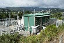 The North Island HVDC terminal station at Haywards near Wellington, showing the Pole 2 converter building and switchyards | |
| Location | |
| Country | New Zealand |
| General direction | South-North |
| From | Benmore Hydroelectric Power Station, near Otematata, Canterbury |
| To | Haywards transmission substation, Lower Hutt |
| Ownership information | |
| Owner | Transpower New Zealand Limited |
| Operator | Transpower New Zealand Limited |
| Construction information | |
| Manufacturer of substations | ABB Group / Siemens |
| Construction started | 1961 |
| Commissioned | April 1965 |
| Technical information | |
| Type | Bipole HVDC scheme with overhead transmission line and Submarine power cables across the Cook Strait |
| Type of current | HVDC |
| Total length | 610 km (380 mi) |
| Power rating | 1200 MW |
| AC Voltage | 220 kV |
| DC Voltage | ±350 kV |
| Number of poles | Two |
The 1200 MW HVDC Inter-Island link is a 610 kilometres (380 mi), bipolar high-voltage direct current (HVDC) transmission system connecting the electricity networks of the North and South Islands of New Zealand together. It is commonly referred to as the Cook Strait cable, which is somewhat of a misnomer, because only a short section of the complete link is in cable, and there are actually three operational HVDC power cables across Cook Strait. However, the term Cook Strait cable is commonly used in the media and press releases.[1] The link is owned and operated by state-owned transmission company Transpower New Zealand.
The link starts at the Benmore Hydroelectric Power Station, on the Waitaki River in Canterbury, and travels 534 kilometres (332 mi) on an overhead transmission line through inland Canterbury and Marlborough to Fighting Bay in the Marlborough Sounds. From Fighting Bay, the link travels 40 km via submarine cables across Cook Strait to Oteranga Bay, near Wellington, before travelling the final 37 km on overhead lines to Haywards transmission substation in Lower Hutt.
The HVDC link was first commissioned in April 1965 to primarily transport electricity from the generation-rich South Island to the more populous North Island. The link originally was a bipolar 600 MW link with mercury arc valves, until the original equipment was paralleled onto a single pole (Pole 1) in 1992, and a new thyristor-based pole (Pole 2) was commissioned alongside it, increasing the link capacity to 1040 MW. Pole 1 was fully decommissioned effective 1 August 2012, and the replacement thyristor-based Pole 3 was fully commissioned on 29 May 2013,[2] restoring the link to a bipolar 1200 MW configuration .
Route
The HVDC Inter Island link starts at two converter stations located adjacent to Benmore Hydroelectric Power Station in the Waitaki Valley. Electricity is taken from the main Benmore switchyard, which interconnects the Benmore generators and rest of the South Island transmission grid, at 220 kV via tie-lines across the Benmore tailrace. The AC power is converted at the stations to ±350 kV HVDC for transmission to the North Island.
A small transmission line carries a twin conductor electrode circuit from the Benmore converter station site to the South Island land electrode at Bog Roy, which in conjunction with the shore electrode in the North Island, allows one pole to operate using earth return when the other pole is out of service.
The HVDC transmission line crosses the Benmore power station tailrace and takes a route along the eastern side of the dam. The line continues north along the eastern shore of Lake Benmore, before turning north-east and then east to meet the Christchurch to Twizel HVAC line. Crossing State Highway 8 south of Fairlie, the line then turns northeast, passing between Fairlie and Geraldine. North of Geraldine to Oxford, the HVDC line broadly follows the Inland Scenic Route tourist highway through the inland Canterbury Plains, passing close to the towns of Methven, Sheffield and Oxford, before continuing northeast towards Waipara.
The line passes through Weka Pass into the Amuri district, travelling north through the region, west of Culverden, to Hanmer Springs. From here, the line turns north-east and travels through Molesworth Station into Marlborough and down the Awatere River valley, before turning north to meet State Highway 1 through the Dashwood and Wards Passes. The line travels east of Blenheim, meeting the eastern coast of the island at Cloudy Bay, and travelling up the coast into the Marlborough Sounds. The line turns east and then south-east around Port Underwood, before crossing to Fighting Bay on the coast, where the South Island cable terminal is located.
At the terminal, the lines connects to three undersea cables taking electricity across Cook Strait. As of August 2012, Pole 2 uses two of these cables, with the third cable unused waiting the commissioning of Pole 3. The cables initially head south out of Fighting Bay, before turning east towards the North Island, and then turning north-east towards the North Island cable terminal at Oteranga Bay.
From Oteranga Bay, the North Island transmission line travels north-east through Makara to the west of Johnsonville. West of Ngaio, the electrode line from the North Island shore electrode at Te Hikowhenua, north of Makara Beach, merges with the main transmission line towers for the final connection to the North Island converter station. The line turns eastwards around Churton Park, crossing to Horokiwi before turning north-east and passing through Belmont Regional Park to Haywards in northern Lower Hutt, the site of the North Island static inverter plant.
At Haywards, two converter stations receive HVDC power at ±350 kV, and convert it to alternating current at 220 kV AC. From here, the power from the Inter Island link flows to the main Haywards HVAC substation, where it is distributed to the Wellington urban area, or is transmitted north to the rest of the North Island grid.
Justification for the line
The HVDC link is an important component of the transmission system in New Zealand. It connects the transmission grids of the two islands, and is used as an energy-balancing system, helping to match energy availability and demand in the two islands.
The two islands are geographically different – the South Island is 33% larger than the North Island in land area (151,000 km2 vs 114,000 km2), but the North Island has over three times the population of the South Island (3.39 million vs 1.04 million). As a consequence, the North Island has a substantially larger energy demand. However, the South Island uses more electricity per capita due to its cooler climate (according to the 2006 Census, 75% of New Zealand households use electricity to heat at least part of their home[3]) and the presence of the Tiwai Point Aluminium Smelter, which at a peak demand of 640 MW is New Zealand's largest single electricity user, and the second largest load centre after the city of Auckland.[4] In 2011, around 37.1% of the total electricity generated was consumed in the South Island, while 62.9% was consumed in the North Island. South Island generation accounted for 40.9% of the nation's electricity in 2011, nearly all (97%) from hydroelectricity, while the North Island generated the remaining 59.1% from a mixture of mainly hydroelectric, natural gas and geothermal generation, plus smaller amount of coal and wind generation.[5]
If all currently commissioned generation is available, both islands have enough generating capacity at peak times, without the connection between the two islands.[6] However, the HVDC link provides benefits for customers in both the South Island and North Island:
- The link provides the South Island consumers with access to the North Island's thermal generation resources that can support the South Island demand during times of low hydro storage levels and low inflows to South Island hydro lakes.
- The link provides North Island consumers with access to the South Island's large hydro generation resources that can support the North Island demand at times of peak load.
The link plays an important role in the New Zealand electricity market, and allows North and South Island generators to compete with each other, therefore driving wholesale electricity prices down.[4]
The inter-island transmission system was designed as an HVDC system, despite the cost of the conversion from AC to DC and back, to suit the requirements of a long transmission line and a sea crossing. The link crosses Cook Strait, between the two islands, using submarine power cables laid along the sea floor. HVDC is more suitable than AC for transmission over long distances, and particularly where cable transmission is required, because it is typically more economic, and has lower energy losses, despite the high costs of the AC/DC conversion process.[7]
Constraints
The link is designed to be able to transmit electricity in both northwards and southwards directions, but the design of the transmission system in the lower North Island restricts the amount of electricity that can be transmitted southwards. The North Island's electricity system has most of its generation in the centre of the island, while the two major load centres, Auckland and Wellington, are located north and south of the main generation resources. The HVDC Inter-Island link connects to the North Island AC transmission system at Haywards in Wellington. The Wellington region is a major load centre with a regional peak demand of approximately 780 MW. Local generation capacity is only 165 MW, and the majority of that is wind power, which is intermittent and cannot be relied on to cover load when required, meaning the region must import electricity to meet demand.
During periods of northwards power flow on the HVDC link, the energy from the South Island is largely used in the Wellington region, and any surplus flows along five lines - four 220 kV lines via the Kapiti Coast and one 110 kV line via the Wairarapa, north to Bunnythorpe near Palmerston North. However, during periods of southwards HVDC flow, the 220 kV lines into Wellington must transmit electricity from the North Island grid for both Wellington and the HVDC link. The 110 kV line is normally unavailable for through transmission into Wellington due to a low circuit rating on the Bunnythorpe to Woodville section, necessitating the line to be split into two near Pahiatua to prevent the low-capacity section overloading and constraining all transmission into Wellington. Southwards HVDC power transfer therefore is limited by the capacity of the lower North Island 220 kV transmission circuits, and by the risk of voltage disturbances in the Wellington region in the event of a sudden disruption to HVDC transfer. The HVDC control and protection systems are also interlocked to prevent operators from operating the link with southbound flow in excess of the difference between the capacity of transmission lines into Haywards and Wellington's minimum regional load. Large southwards transfers on the HVDC link are not generally required except during period of prolonged low inflows to South Island hydro lakes, and the limited southbound capacity is not a major constraint.[4]
Northbound transfer is not usually constrained, but can become constrained if one of the 220 kV lines out of Wellington or through the Central North Island becomes overloaded or is out of service.
History
Planning
The initial vision for electricity transmission between the South and North Islands was developed by Bill Latta, the Chief Engineer of the State Hydro-electric Department. In 1950, he prepared a paper on the future of the North Island's electric power supply and drew attention to the projected load growth and the limited potential for further North Island hydro-electric generation development. Latta's vision was to build more hydro generating capacity in the South Island, where there was still significant opportunities for new schemes, and transmit the power to the southern half of the North Island to meet the increasing demand.[8]
In 1951, the cable manufacturing company British Insulated Callender's Cables (BICC) advised the State Hydro-Electric Department that a cable crossing of Cook Strait was possible, but difficult, since there was no precedent for installing power cables in such difficult marine conditions.[9]
The development of high power mercury arc valve converters in the 1950s led to the development of several HVDC transmission schemes in other countries. This demonstrated that a long distance, high power HVDC transmission scheme was feasible in principle. See HVDC#Mercury arc valves.
In 1956, the Government appointed BICC to undertake detailed investigations of the practicality and cost of a Cook Strait cable crossing. In December of that year, BICC reported that the project was "thoroughly practicable".[10]
In parallel with the technical investigations for cables across Cook Strait, the Minister responsible for the State Hydro-Electric Department appointed a committee of key stakeholders to report on the options for power supply to New Zealand as a whole, not just the North Island. In 1957, the committee recommended that work commence on a large hydro-electric power station on the Waitaki River at Benmore, and that approval in principle should be given for linking the North and South Island's power systems.
Recommendations were also received from the Swedish company ASEA (today part of the ABB Group), about the technical aspects of the HVDC converter stations.
The unique planning considerations for the overall proposal included:[8]
- The hydro-generators at Benmore would need to be capable of absorbing the harmonic currents that would be created by the operation of the mercury arc converters
- The Benmore generators were proposed to have an operating voltage of 16 kV, which was a new high for New Zealand hydro generators at the time
- The 16 kV circuit breakers required at Benmore would be state of the art
- The mercury arc valves would be larger than any previously constructed, and would require water-cooled cathodes
- The overhead HVDC transmission line would be one of the longest and most difficult built in New Zealand up to that time
- The Cook Strait submarine cables would have to be specially designed for the seabed and tidal conditions, and require special armouring at the Oteranga Bay end, of a kind that had not been used before
In 1958, BICC laid two 0.8 km trial lengths of cable off Oteranga Bay in Cook Strait to demonstrate their ability to resist the abrasion, bending and vibration caused by conditions on the seabed. These trial lengths were recovered and inspected in 1960, and by October that year, BICC reported that the trial had been successful and that the prototype cable would provide good service across Cook Strait.[8]
In the period 1958 to 1960, some differing views were offered to Government about the most appropriate power developments for the country as a whole, and there were reservations about the risks involved in the planned Cook Strait cable crossing.[9]
However, in March 1961, against a background of increasing urgency in meeting forecast demand, the Government approved the project. A NZ£6.5 million contract was placed with ASEA for the design, manufacture, installation and commissioning of the converter plant at Benmore and Haywards, and a NZ£2.75 million contract was placed with BICC for the manufacture, delivery, laying and testing of the Cook Strait submarine cables.[8]
Construction of the original inter-island scheme
The HVDC inter-island link was designed and built between 1961 and 1965 for the New Zealand Electricity Department. The major equipment suppliers were ASEA and British Insulated Callender's Cables.[8] The original Cook Strait cables were installed in 1964, from the cable laying ship Photinia.[11]
When it was completed, the New Zealand HVDC link was the world's longest HVDC transmission scheme, with the highest power rating, and the largest undersea power cables.[12] The terminal stations at each end of HVDC link used large mercury-arc rectifiers and inverters – 1960s technology – to convert between AC and DC. The South Island converter station was established at the Benmore hydroelectric power station in the Waitaki Valley. The North Island converter station was built at Haywards in the Hutt Valley near Wellington.
The HVDC transmission line that connects Benmore and Haywards converter stations has an overall length of 610 kilometres. The overhead transmission line is supported by 1649 transmission towers and has a total route length of 570 km. The submarine cables across Cook Strait are 40 km long.[13]
Until it was upgraded in 1993, the HVDC Inter-Island link had normal operating voltages of ±250 kV, and a maximum power transmission capacity of about 600 MW.
The HVDC link was originally designed to transfer power northwards from Benmore to Haywards. In 1976, the control system of the original scheme was modified to allow power to be sent in the reverse direction, from Haywards to Benmore.[8]
Hybrid Upgrade Project

In 1987, the Electricity Corporation of New Zealand began investigations to find the best means of upgrading the inter-island link. A hybrid upgrade was chosen over total replacement, for economic reasons. The term "hybrid" was adopted because the increase in capacity was to be obtained through a combination of voltage and current upgrades. The upgrade project involved continued use of the existing mercury arc valve converter equipment alongside new solid state thyristor converter stations. The scope of work included:[10]
- Providing three new HVDC submarine cables across Cook Strait, to supplement and ultimately replace the original cables. Each new cable was rated at 350 kV, 1430 A, giving a maximum power capacity of 500 MW per cable. The three new power cables were installed in 1991 by the specialist cable laying vessel Skagerrak.[14]
- New cable terminal stations at Fighting Bay and Oteranga Bay
- The existing mercury arc valve converters at each end of the link were re-configured to operate in parallel at each station (they had previously operated with opposite electrical polarity). They were re-designated as Pole 1.
- The operating voltage of the mercury arc valve converters was increased from the original 250 kV to 270 kV
- New HVDC thyristor converter stations were added at each end of the link. These had an operating voltage of 350 kV, and were designated as Pole 2.
- Re-insulation of the entire HVDC overhead transmission line to increase its rating to 350 kV. Work on transmission structures and conductors was also carried out to ensure that the line conductors could operate at up to 2000 A on each Pole.
The Pole 2 converter stations and new submarine cables were commissioned in March 1991.
The upgrade brought the total converter station capacity to 1348 MW (648+700 MW), however the link was restricted to 1240 MW due to the overhead transmission line rating restricting Pole 1's operating capacity to 540 MW. After the retirement of the last of the original submarine cables, the overall HVDC link transfer capability was restricted further to 1040 MW due to the single Pole 2 cable across Cook Strait.[8]
Decommissioning of Pole 1
On 21 September 2007, the original Pole 1 mercury-arc converter stations were stood down "indefinitely". However, in December 2007, Transpower announced that one-half of the capacity of Pole 1 would be returned to "warm standby" service before the winter of 2008 in order to meet the demand for power in the North Island if needed. The remaining half-pole equipment of Pole 1 was to be decommissioned.[15]
Transpower also announced in November 2007 that by December 2007, it would increase the south to north power transmission capacity of Pole 2 from 500 MW to 700 MW. This was done by reconfiguring the three operational submarine cables. One of the two cables previously connected to Pole 1 was transferred to Pole 2.[16]
On 13 March 2008, Transpower announced that work had been completed to restore 50% of the capacity of Pole 1 to service at times when the demand for power on the North Island peaked.[17] Several mercury arc rectifiers were salvaged from the Konti-Skan link between Denmark and Sweden for this restoration. The energy transfer on Pole 1 was strictly limited to the northbound direction, to reduce the stress and strain on the aged converter system.
In May 2009 Transpower placed the remaining capacity of Pole 1 back into service for a short period, at a limited capacity of 200 MW, in response to a temporary loss of capacity on Pole 2.
The decommissioning of half of Pole 1 and the operational restrictions placed on the remaining Pole 1 capacity led to the HVDC link operating mostly in monopolar mode, using Pole 2 alone. In 2010, Transpower reported that continuous operation in monopolar mode has caused the HVDC link to act as a galvanic cell with the earth, causing Benmore's Bog Roy earth electrodes to erode as they acted as an anode, and causing the buildup of magnesium and calcium hydroxide deposits on Hayward's Te Hikowhenua shore electrodes as they acted as a cathode. Additional replacement and maintenance works were required.[13]
On 1 August 2012, Transpower decommissioned the remaining half of the Pole 1 mercury arc valve converter stations at Benmore and Haywards, after 47 years in service.[18] The Inter Island link at the time was the last HVDC system in the world with mercury arc valve converters in operational service.
Transmission faults and outages
Like all transmission systems, the HVDC Inter-Island link is not immune to failures. The importance of the link means that an unplanned outage can have major implications for the whole of the New Zealand electricity system, potentially causing nationwide frequency deviation (underfrequency in the receiving island, overfrequency in the other island), electricity shortages in the receiving island, and a spike in wholesale electricity prices. The most catastrophic situation is a simultaneous bipole outage at high transfer when there is low to medium generation in the receiving island - instantaneous reserve generation and load shedding systems in the receiving island would not be able to come online fast enough to prevent the frequency dropping, resulting in cascading failure and outage of the entire receiving island.[19]
To ensure security of the link's submarine power cables, a seven-kilometre wide Cable Protection Zone (CPZ) is enforced where the cables cross Cook Strait. Vessels are not permitted to anchor or fish in this area, and the area is routinely patrolled by sea and air. Anyone found anchoring or fishing in the area is liable for fines up to $100,000 and forfeiture of their vessel – more if a cable is subsequently damaged.[20]
Planned outages of the link are required occasionally to carry out maintenance that is not possible while the system is live. Maintenance outages are planned well in advance to minimise the effects – they are usually carried out in summer when national electricity demand is at its lowest, and on only one pole at a time, with the other pole remaining in operation providing half of the full two-pole capacity, utilizing the earth electrodes providing a path for return current through the ground.
Notable faults and outages on the HVDC Inter-Island link:
- 1973 – an electrical fault occurred in the shore joint of Cable 1 at Fighting Bay.[10]
- August 1975 – A strong wind storm caused a string of seven transmission towers to collapse and damage the line. The link took five days to repair.[10]
- 1976 – A fault occurred at the Cable 1 undersea joint, 15.5 km from the South Island end at a depth of 120 metres. The joint was repaired in 1977.[10]
- 1980 – Cable 3 failed at the Fighting Bay shore joint.[10]
- 1981 – A gas leak on Cable 1 occurred at Oteranga Bay. It was repaired in the 1982/83 summer.[10]
- 1988 – Cable 2's Oteranga Bay end joint exploded, spilling insulating oil into the switchyard.[10]
- 2004 – In January, three HVDC towers collapsed as a result of extreme winds, and in August the line voltage had to be reduced for long periods because of insulation flashovers caused by severe salt pollution at the cable station at Oteranga Bay. In October, a fault occurred in one of three Cook Strait cables that reduced the Pole 1 capacity from 540 MW to 386 MW. Repairs took almost six months.[21]
- 19 June 2006 – The link experienced an unplanned outage just before the evening peak period on one of the coldest days of the year. With four North Island power stations out for service and an outage of Tauranga's ripple load control equipment, even with the reserve Whirinaki Power Station called upon, the North Island experienced electricity shortages and Transpower subsequently declared a nationwide Grid Emergency at 5:34 pm. The link was restored shortly after the emergency was declared.[10]
- 28 August 2008 – A transmission tower in the Marlborough Sounds was found buckled after its foundations slipped. The tower was reinforced with steel guy ropes until it could be replaced, as the link couldn't be shut down without causing widespread power shortages in the South Island.[22]
- 12 November 2013 – During the commissioning of the new bi-pole control systems, a test to assess the control's response to a trip on a 220 kV line out of Haywards during high north flow caused three filter banks at Benmore to trip off the grid. The HVDC controls automatically cut northbound transfer from 1000 MW to 140 MW, causing automatic under-frequency load shedding (AUFLS) systems to deploy in the North Island and blacking out thousands of customers. A software bug was found to be the cause of the filter bank trips.
Current developments
In May 2008, Transpower submitted an investment proposal to the Electricity Commission for the replacement of the old mercury arc valve Pole 1 converter stations with new thyristor converter stations. In July 2008, the Electricity Commission announced its intention to approve the project.[23]
The Pole 3 Project

This project involved the construction of new converter stations designated as Pole 3, to operate at +350 kV 700 MW, matching the existing Pole 2 (−350 kV, 700 MW). Site works on the $672 million project were formally commenced on 19 April 2010, when Minister of Energy Gerry Brownlee turned the first sod. The new converter stations were to be commissioned by April 2012,[24] but in May 2011, Transpower announced that commissioning was delayed until December 2012 because of difficulties being experienced by the manufacturer. [25]
Work involved in replacing Pole 1 with the new Pole 3 converter stations included:[4]
- New valve halls adjacent to the Pole 2 valve halls at both Benmore and Haywards, each containing the thyristors converters
- New transformers connecting the valve halls to the 220 kV buses at both Benmore and Haywards
- Connecting the Pole 3 thyristors to the existing Pole 1 lines at both Benmore and Haywards
- Connecting the Pole 3 thyristors to the existing electrode lines at both Benmore and Haywards
- Switching the number 5 Cook Strait cable from Pole 2 back to the Pole 1/3.
- New 220 kV filters on the 220 kV buses at both Benmore and Haywards
- New transformers connecting the four synchronous condensers C7 to C10 to the 110 kV bus at Haywards
- New 5th and 7th harmonic filters connecting to the 110 kV bus at Haywards.
- Removal of the existing converter transformers connecting the Pole 1 mercury arc valves and two of the synchronous condensers to the 110 kV bus at Haywards.
- Removal of all remaining mercury arc valve Pole 1 equipment at both Benmore and Haywards.

The decommissioning of Pole 1 was scheduled for July 2012, allowing works to switch the existing lines over Pole 3 to occur, and allow testing of the new pole to occur during the summer months where electricity demand and therefore inter-island electricity transfer is low. The new Pole 3 will be able to operate at 700 MW from commissioning, but due to inadequate voltage support at the Haywards end of the link, Pole 2 and 3 combined transfer will be limited to 1000 MW. After the commissioning of a new static synchronous compensator (STATCOM) at Haywards, planned for January 2014, Pole 3 will be able to operate at its full capacity with Pole 2 in operation (1200 MW total transfer).[26]
Pole 2 control system replacement
Pole 2 was commissioned in 1992 with HVDC control systems utilising late 1980s technology. After 20 years in service, the control systems are nearing the end of their useful life, are technologically obsolete, and are incompatible with the new Pole 3 control systems, making bipole control impossible.
In late 2013, Transpower is to take Pole 2 out of service for four weeks to allow the control systems to be replaced with new systems identical to those used in Pole 3, and to install a new bipole control system to control both poles. This will be followed by three months of testing the new control systems. Pole 3 will continue to operate during the outage and most of the testing in a monopolar configuration with the earth electrodes.
Other associated works
Line maintenance
During the Pole 1 replacement, work is also underway to carry out maintenance and remedial work on some sections of the transmission line. Work includes:[26]
- Replacing around 100 transmission towers in the South Island to fix clearance issues
- Replacing some conductor lengths in the North Island as they approach the end of their useful life
- Reinforcing some North Island transmission towers.
Benmore generator transformers
The original design of the inter-island link at Benmore was integrated with the design of the 540 MW Benmore hydroelectric power station. The 16 kV generator busbars in the power station were the point of connection between the HVDC link and the South Island grid. The power from the six Benmore generators could flow directly from the 16 kV busbars to the HVDC link via converter transformers, with the interconnecting transformers connecting to the Benmore 220 kV busbar to export or import electricity from the rest of the South Island. The design of the power station was optimised with the HVDC link, and the interconnecting transformers were designed with a significantly lower rating than the maximum output of the Benmore generators, because so much of the generator output power would normally flow to the HVDC link.
Following Transpower's decommissioning of the original Pole 1 equipment, there was no longer any direct connection between the generator 16 kV busbars and the HVDC link, and the limited capacity of the Benmore interconnecting transformers would have constrained the maximum output of the station. In co-ordination with the Transpower programme for decommissioning of the Pole 1 equipment, Benmore owner Meridian Energy replaced the interconnecting transformers with new generator transformers. The six generators were reconnected to the 220 kV national grid via six new generator circuit breakers and three 220/16/16 kV three winding transformers. The new transformers each connect two generators, via two 16 kV secondary windings.[27] [28]
Technical description

The New Zealand Inter-Island HVDC link is a long distance bipolar HVDC "Classic" transmission scheme that uses overhead lines and submarine cables to connect between the South and North Islands. It utilises thyristor-based line-commutated converters at each end of the link for rectifying and inverting between AC and DC. The link includes ground electrode stations that enable the use of earth return current. This permits operation with unbalanced current between the two poles, and monopolar operation when one pole is out of service.
Converter stations
The converter stations for each pole, at each end of the link include:
- converter valve hall, cooling system and control building
- converter transformers
- 220 kV AC switchyard equipment and connections
- 220 kV AC harmonic filters
- 350 kV DC switchyard equipment, including DC smoothing reactor
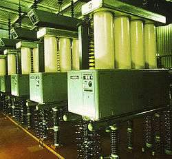
The converter valves are twelve-pulse converters, arranged as three water-cooled quadrivalve assemblies. Both Pole 2 and Pole 3 use a design that suspends the quadrivalves from the roof of the valve hall. This provides superior seismic performance compared with a ground mounted arrangement, especially in New Zealand's highly seismic environment.[29] There are three single phase converter transformers for each converter valve, and each transformer has two secondary windings connected to the valve.
Details of the converter station equipment and ratings are given in the table below:[30]
| Converter Station | Pole 2 | Pole 3 | Notes |
|---|---|---|---|
| Commissioned | 1991 | May 2013 | |
| Manufacturer | Asea Brown Boveri (ABB) | Siemens | |
| Operating voltage | −350 kV | +350 kV | |
| Converter nominal rating | 560 MW | 700 MW | |
| Converter continuous overload rating | 700 MW | 735 MW | |
| Short term overload rating | 840 MW for 5 s | 1000 MW for 30 min | |
| Thyristor type | 4" (100 mm) diameter, electrically triggered, water cooled | 5" (125 mm) diameter, light triggered, water cooled | |
| Valve maximum continuous current rating | 2,000 A | 2,860 A | |
| Thyristor peak reverse voltage | 5.5 kV | >7.5 kV | |
| Thyristors per valve | 66 | 52 | |
| Thyristors per quadrivalve unit | 264 | 208 | |
| Thyristors per station | 792 | 624 | |
| Quadrivalve mass | 20 tonnes | 17 tonnes | |
| No of converter transformers | 8 total: 3 plus 1 spare at each converter station | 8 total: 3 plus 1 spare at each converter station | |
| Converter transformer mass | 324 tonnes, including oil | 330 tonnes, including oil | |
| Oil volume per transformer | 85,000 litres (19,000 imp gal; 22,000 US gal) | 91,000 litres (20,000 imp gal; 24,000 US gal) | |
Submarine cables

The three submarine power cables installed in 1991 are each rated to carry 1430 A continuously at 350 kV operating voltage. They are constructed with a compacted multi-strand copper conductor as a central core, with mass-impregnated paper insulation surrounded by a lead sheath. Two layers of galvanised steel wire armour provides strength and mechanical protection. The outer layer of the cable is a serving made from polypropylene rope and the outer diameter is approximately 130 mm. The cables have a 30-minute overload capacity of 1600 A.[29]
HVDC transmission line
_line.jpg)

The transmission line was designed and built by the New Zealand Electricity Department, and was completed in January 1965. The original construction of the line included the erection of 1623 steel lattice towers. In some South Island sections, the line reaches an altitude of 1280 metres. The longest span is 1119 m, near Port Underwood, close to the Fighting Bay cable terminal station.
The line was originally designed for operation at ±250 kV. During the DC Hybrid link project of 1989 to 1992, the transmission line was re-insulated with DC fog type porcelain insulator units, to enable operation at 350 kV. There are 15 units per insulator string in the inland parts of the route, and 33 units per insulator string in the coastal parts of the route that are exposed to salt pollution. The insulator strings in the coastal portions are around 5 m long.[29]
The transmission line insulators support a pair of ACSR conductors on each side of the towers. The conductors are each 39.4 mm in diameter, and are spaced 432 mm apart. [8]
The line has a continuous overhead earthwire for lightning protection, except for a 21 km section at the Haywards end, where the line is shielded by the electrode line conductors. A 13 km section of the North Island HVDC line uses an overhead earthwire containing a fibre optic core (OPGW), and a further 169 km section of OPGW is installed the South Island line.[29]
Approximately 20 new towers were constructed in 1992 to re-route the HVDC line north of Johnsonville to make way for new residential development. This was known as the Churton Park deviation.[31]
Around 92.5% (1503) of the towers on the line in 2010 were identified as being original, with the remaining towers having been replaced due to line deviations, collapse, or corrosion.
Following the DC Hybrid Link project, the line was rated to carry 2000 A continuously on each pole, at an operating voltage of 350 kV HVDC.
Earth electrode stations
The connection between the North Island converter station and earth uses a shore electrode station located at Te Hikowhenua, approximately 25 km from Haywards. Following upgrades carried out during the DC Hybrid Link project, the electrode station is capable of carrying 2400 A continuously. Forty electrode cells are buried along an 800 m length of a stony beach. Each electrode cell consists of a high silicon-chromium iron electrode, suspended in a vertical porous concrete cylinder. The cells are surrounded by selected and graded stones and geo-textile layers to allow seawater ingress, but prevent the buildup of silt. The electrode to ground resistance is 0.122 Ω.[29]
The South Island ground electrode station is located at Bog Roy, 7.6 km from Benmore. It comprises buried electrode arms arranged in a star configuration over a site of approximately 1 km2. Each electrode arm is a 40 mm mild steel rod buried in a coke bed of around 0.26 m2 cross sectional area, in a 1.5 m deep trench. The electrode to ground resistance is 0.35 Ω.[29]
Future developments
Fourth Cook Strait cable
There are proposals to install a fourth cable across the Cook Strait (Cable 7), connecting to Pole 2, to allow the HVDC link to increase to 1400 MW. In addition to a fourth cable, new filters would also be installed at Benmore and Haywards, and a new STATCOM at Haywards. The project is unlikely to be completed before 2016.
North Canterbury tap
The Upper South Island north of the Waitaki Valley is generation-poor, yet has many large demand centres, especially Christchurch, Nelson, Ashburton and Timaru-Temuka. Almost all of the electricity has to be imported from the Waitaki Valley, via three major 220 kV lines: the single-circuit Livingstone to Islington line (built 1956), the single-circuit Twizel to Islington via Tekapo B line (built 1962), and the double-circuit Twizel to Islington/Bromley via Timaru and Ashburton line (built 1975). Increasing demand and changing usage patterns, largely attributed to land use changes and increased irrigation in Canterbury, means that these lines are fast approaching capacity, and because they all converge on Islington sub-station in western Christchurch, a major fault at the sub-station could potentially interrupt the electricity supply to the entire South Island north of Christchurch.
One of the many proposals to alleviate this issue includes a tap into the HVDC Inter-Island and an inverter/rectifier station where it meets the two 220 kV Islington to Kikiwa lines near Waipara in North Canterbury. This would allow another route for electricity into Christchurch and the Upper South Island, and create redundancy in the network. However, due to its large cost and there being more cost-effective solutions to secure electricity supply in the short-to medium term, it is unlikely for such a tap to be built before 2027.[32]
Sites
- Haywards HVDC Converter Station: 41°09′05″S 174°58′54″E / 41.151446°S 174.981691°E
- Te Hikowhenua deviation line take-off point: 41°14′03″S 174°45′31″E / 41.234167°S 174.758611°E
- Te Hikowhenua Shore Electrode Station: 41°12′28″S 174°43′11″E / 41.20778°S 174.71972°E
- Oteranga Bay Cable Terminal Station: 41°17′37″S 174°37′48″E / 41.29361°S 174.63000°E
- Fighting Bay Cable Terminal Station: 41°18′35″S 174°12′07″E / 41.3098°S 174.202°E
- Bog Roy Land Electrode Station: 44°34′26″S 170°05′56″E / 44.574°S 170.099°E
- Benmore HVDC Converter Station: 44°33′55″S 170°11′24″E / 44.56528°S 170.19000°E
See also
- National Grid (New Zealand)
- High-voltage direct current
- List of HVDC projects
- Electricity sector in New Zealand
References
- ↑ "Cook Strait Cable Power Failure". The New Zealand Government. 28 April 2009. Retrieved 28 September 2011.
- ↑ "New HVDC Pole 3 Commissioned". Transpower New Zealand. 29 May 2013. Retrieved 1 June 2013.
- ↑ "Heating fuels -- QuickStats about Housing -- 2006 Census". Statistics New Zealand. Retrieved 28 March 2013.
- 1 2 3 4 "Annual Planning Report 2012" (PDF). Transpower. April 2012. Retrieved 30 August 2012.
- ↑ "New Zealand Energy Data File 2012" (PDF). Ministry of Economic Development. June 2012. Retrieved 6 July 2012.
- ↑ "HVDC Grid Upgrade Plan Volume 1, p10" (PDF). May 2008. Retrieved 2 September 2012.
- ↑ "High Voltage Direct Current". United States Energy Association. Archived from the original on 13 August 2010. Retrieved 11 March 2012.
- 1 2 3 4 5 6 7 8 Taylor, Peter (1990). White Diamonds North: 25 Years' Operation of the Cook Strait Cable 1965–1990. Wellington: Transpower. pp. 109 pages. ISBN 0-908893-00-0.
- 1 2 Martin, John E, ed. (1998). People, Politics and Power Stations: Electric Power Generation in New Zealand 1880–1998 (Second ed.). Wellington: Bridget Williams Books Ltd and Electricity Corporation of New Zealand. p. 356. ISBN 0-908912-98-6.
- 1 2 3 4 5 6 7 8 9 Reilly, Helen (2008). Connecting the Country: New Zealand's National Grid 1886–2007. Wellington: Steele Roberts. pp. 376 pages. ISBN 978-1-877448-40-9.
- ↑ "The original Cook Strait cable is hauled ashore at Ōteranga Bay on Wellington's south-west coast in 1964". Te Ara: The Encyclopedia of New Zealand. Retrieved 20 September 2011.
- ↑ Engineering to 1990 – IPENZ, Engineering Publications Co Ltd, Page 38
- 1 2 "Asset Management Plan" (PDF). Transpower. April 2010.
- ↑ "Extending the Skagerrak". Ship-Technology.com. Retrieved 28 September 2011.
- ↑ "Transpower Decommissions Half Of Pole 1". Scoop. 19 December 2007.
- ↑ "Geothermal plant in Contact's Taupo plan". NZ Herald. 20 November 2007. Retrieved 3 October 2011.
- ↑ "Transpower gets green light to restore inter-island link". NZ Herald. 13 March 2008.
- ↑ "Pole 1 decommissioned". Transpower. 31 August 2012. Retrieved 3 September 2012.
- ↑ "Automatic Under-Frequency Load Shedding (AUFLS) Technical Report" (PDF). Transpower New Zealand. August 2010. Retrieved 7 June 2012.
- ↑ Cook Strait Submarine Cable Protection Zone (PDF). Transpower New Zealand and Maritime New Zealand. February 2011. Retrieved 20 May 2012.
- ↑ Transpower (2005), Quality Performance Report 2004-05
- ↑ "Power supply safe, unless it's windy". The New Zealand Herald. 30 August 2008. Retrieved 23 July 2011.
- ↑ "HVDC Upgrade Proposal". Electricity Commission. 31 July 2008.
- ↑ "Ceremony marks start of electrical construction on Pole 3 project". Transpower. 19 April 2010. Retrieved 30 August 2012.
- ↑ "Transpower Notice - Commissioning of HVDC Pole 3". Transpower. 11 May 2011. Retrieved 30 August 2012.
- 1 2 "HVDC inter-Island link project – Grid New Zealand". Transpower New Zealand. Retrieved 30 August 2012.
- ↑ "An Iconic Reconfiguration (Benmore Power Station)" (PDF). PBA Electrical Contractors. 3 May 2011. Retrieved 2 July 2012.
- ↑ "Benmore gets more with first full rebuild". Otago Daily Times. 30 October 2008. Retrieved 2 July 2012.
- 1 2 3 4 5 6 O'Brien, M T; Fletcher, D E; Gleadow, J C (29 September 1993). Principal Features of the New Zealand DC Hybrid Link. Wellington: CIGRE. International Colloquium on High Voltage Direct Current and Flexible AC Power Transmission Systems.
- ↑ Griffiths, Peter; Zavahir, Mohamed (27 May 2010). "NZ Inter Island HVDC Pole 3 Project Update" (PDF). Christchurch. EEA Conference & Exhibition 2010. Retrieved 27 May 2012.
- ↑ "OTB-HAY A Re-conductoring Project" (PDF). Transpower. 26 October 2010. Retrieved 2 June 2012.
- ↑ "Annual Planning Report 2012 - Chapter 6 – Grid Backbone" (PDF). Transpower New Zealand. March 2012. Retrieved 30 August 2012.
External links
| Wikimedia Commons has media related to HVDC Inter-Island. |
- New Zealand's HVDC Link
- New Zealand HVDC – the interisland link (from the ABB website)
- http://web.archive.org/web/20050526185217/www.transmission.bpa.gov/cigresc14/Compendium/NEW-ZEAL.htm
- http://web.archive.org/web/20050526185217/www.transmission.bpa.gov/cigresc14/Compendium/New-zeal%20Pictures.pdf