Group code recording
In computer science, group code recording (GCR) refers to several distinct but related encoding methods for magnetic media. The first, used in 6250 cpi magnetic tape, is an error-correcting code combined with a run length limited encoding scheme. The others are different floppy disk encoding methods used in some microcomputers until the late 1980s.
GCR for 9-track reel-to-reel tape
In order to reliably read and write to magnetic tape, several constraints on the signal to be written must be followed. The first is that two adjacent flux reversals must be separated by a certain distance on the media. The second is that there must be a flux reversal often enough to keep the reader's clock in phase with the written signal; that is, the signal must be self-clocking. Prior to 6250 cpi tapes, 1600 cpi tapes satisfied these constraints using a technique called phase encoding, which was only 50% efficient. For 6250 GCR tapes, a (0,2)RLL code is used. This code requires five bits to be written for every four bits of data. The code is structured so that no more than two zero bits (which are represented by lack of a flux reversal) can occur in a row, either within a code or between codes, no matter what the data was. This RLL code is applied independently to the data going to each of the 9 tracks.
Of the 32 5-bit patterns, 8 begin with two consecutive zero bits, 6 others end with two consecutive zero bits, and one more (10001) contains three consecutive zero bits. Removing the all-ones pattern (11111) from the remainder leaves 16 suitable code words.
The 6250 GCR RLL code:
| Nibble | Code | Nibble | Code | |
|---|---|---|---|---|
| 0000 | 11001 | 1000 | 11010 | |
| 0001 | 11011 | 1001 | 01001 | |
| 0010 | 10010 | 1010 | 01010 | |
| 0011 | 10011 | 1011 | 01011 | |
| 0100 | 11101 | 1100 | 11110 | |
| 0101 | 10101 | 1101 | 01101 | |
| 0110 | 10110 | 1110 | 01110 | |
| 0111 | 10111 | 1111 | 01111 |
11 of the nibbles (other than xx00 and 0001) have their code formed by prepending the complement of the msbit; i.e. abcd is encoded as a̅abcd. The other 5 values are assigned codes beginning with 11. Nibbles of the form ab00 have codes 11baa̅, i.e. the bit reverse of the code for ab11. The code 0001 is assigned the remaining value 11011.
Because of the extremely high density of 6250 cpi tape, the RLL code is not sufficient to ensure reliable data storage. On top of the RLL code, an error-correcting code called the Optimal Rectangular Code (ORC) is applied. This code is a combination of a parity track and polynomial code similar to a CRC, but structured for error correction rather than error detection. For every 7 bytes written to the tape (before RLL encoding), an 8th check byte is calculated and written to the tape. When reading, the parity is calculated on each byte and exclusive-or'd with the contents of the parity track, and the polynomial check code calculated and exclusive-or'd with the received check code, resulting in two 8-bit syndrome words. If these are both zero, the data is error free. Otherwise, error-correction logic in the tape controller corrects the data before it is forwarded to the host. The error correcting code is able to correct any number of errors in any single track, or in any two tracks if the erroneous tracks can be identified by other means.
IBM documents refer to the error correcting code itself as "group coded recording". However, GCR has come to refer to the recording format of 6250 cpi tape as a whole, and later to formats which use similar RLL codes without the error correction code.
GCR for floppy disks
Like magnetic tape drives, floppy disk drives have physical limits on the spacing of flux reversals (also called transitions, represented by 1 bits).
For the Apple II floppy drive, Steve Wozniak invented a floppy controller which (along with the drive itself) imposed two constraints
- Between any two one bits, there may be a maximum of one zero bit.
- Each 8-bit byte must start with a one bit.
The simplest scheme to ensure compliance with these limits is to record an extra "clock" transition before each data bit. This scheme is called differential Manchester encoding or FM (Frequency Modulation) or "4 and 4", and allows only 10 256-byte sectors per track to be recorded on a single-density 5¼ floppy.
Wozniak realized that a more complex encoding scheme would allow each 8-bit byte on disk to hold 5 bits of useful data rather than 4 bits. This is because there are 34 bytes which have the top bit set and no two zero bits in a row. This encoding scheme became known as "5 and 3" encoding, and allowed 13 sectors per track; it was used for Apple DOS 3.1, 3.2, and 3.2.1, as well as for the earliest version of Apple CP/M. Later, the design of the floppy drive controller was modified to allow a byte on disk to contain up to one pair of zero bits in a row. This allowed each 8-bit byte to hold 6 bits of useful data, and allowed 16 sectors per track. This scheme is known as "6 and 2", and was used on Apple Pascal, Apple DOS 3.3 and ProDOS, and later on the 400K and 800K 3½ disks on the Macintosh and Apple II. Apple did not originally call this scheme "GCR", but the term was later applied to it to distinguish it from IBM PC floppies which used the MFM encoding scheme.
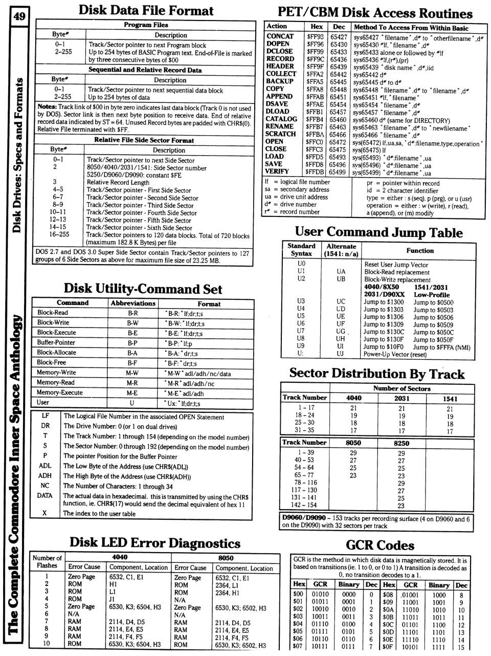
Independently, Commodore Business Machines created a Group Code Recording scheme for their Commodore 2040 floppy disk drive (launched in the spring of 1979). The relevant constraints on the 2040 drive were that no more than two zero bits could occur in a row, nor more than eight one bits in a row; the drive imposed no special constraint on the first bit in a byte. This allowed the use of a scheme similar to that used in 6250 tape drives. Every 4 bits of data are translated into 5 bits on disk, according to the following table:
|
|
Note no code starts with two zero bits, nor ends with two zero bits. This ensures that regardless of the input data, the encoded data will never contain more than two zero bits in a row. Also note that with this encoding not more than eight one bits in a row are possible. Therefore, Commodore used sequences of ten or more one bits in a row as synchronization mark.
This more efficient GCR scheme, combined with an approach at constant bit-density recording by gradually increasing the clock rate (zone constant angular velocity, ZCAV) and storing more physical sectors on the outer tracks than on the inner ones (zone bit recording, ZBR), enabled Commodore to fit 170 kB on a standard single-sided single-density 5.25" floppy, where Apple fit 140 kB (with 6 and 2 GCR) or 114 kB (with 5 and 3 GCR) and an FM-encoded floppy held only 88 kB.
Similar, the 5.25" floppy drives of the Victor 9000 aka Sirius 1, designed by Chuck Peddle, used a combination of 10-bit GCR and constant bit-density recording by gradually decreasing a drive's rotational speed for the outer tracks to achieve formatted capacities of 606 kB (single sided) / 1188 kB (double-sided) on 96 tpi media.[1][2]
See also
- Modified Frequency Modulation (MFM)
- Run Length Limited (RLL)
- Eight-to-Fourteen Modulation (EFM)
- Error-correcting code
- 8b/10b encoding
References
- ↑ Victor 9000/Sirius 1 Specification
- ↑ Victor Supplemental Technical Reference Material. Application Note 2, Level 3, Revision 7, 1983-03-23
- Patel, A.M and Hong, S.J, "Optimal Rectangular Code for High Density Magnetic Tapes", IBM Journal of Research and Development, 18, pp. 579–588 (1974)
- Hsiao, M.Y, et al., "Reliability, Availability, and Serviceability of IBM Computer Systems", IBM Journal of Research and Development, 25, p. 462 (1981) (mentions the 5/4 RLL code used on 6250 tape drives)
- Qualstar 34XX Technical Service Manual pp. 3–4..3-7 (additional detail on the GCR tape format)
- Lechner, Pieter and Worth, Don, Beneath Apple DOS ("5 and 3" and "6 and 2" details)
- Hildon, Karl, The Complete Commodore Inner Space Anthology, p. 49 (Commodore GCR codes—but be warned that this reference erroneously claims that a 1 bit indicates a lack of a transition.)
- Williams, Gregg and Moore, Rob, "The Apple Story", Byte Interview with Steve Wozniak, where he describes creating the Apple version of GCR.
External links
- The PC Guide Frequency Modulation
- The Gallery of Old Iron A comment on the origin of the name "Group Coded Recording".