Friction stir welding

Friction stir welding (FSW) is a solid-state joining process that uses a non-consumable tool to join two facing workpieces without melting the workpiece material. Heat is generated by friction between the rotating tool and the workpiece material, which leads to a softened region near the FSW tool. While the tool is traversed along the joint line, it mechanically intermixes the two pieces of metal, and forges the hot and softened metal by the mechanical pressure, which is applied by the tool, much like joining clay, or dough. It is primarily used on wrought or extruded aluminium and particularly for structures which need very high weld strength.
It was invented and experimentally proven at The Welding Institute (TWI) in the UK in December 1991. TWI held patents on the process, the first being the most descriptive.[1]
Principle of operation


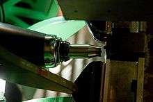
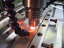
A rotating cylindrical tool with a profiled probe is fed into a butt joint between two clamped workpieces, until the shoulder, which has a larger diameter than the pin, touches the surface of the workpieces. The probe is slightly shorter than the weld depth required, with the tool shoulder riding atop the work surface.[2] After a short dwell time, the tool is moved forward along the joint line at the pre-set welding speed.
Frictional heat is generated between the wear-resistant tool and the work pieces. This heat, along with that generated by the mechanical mixing process and the adiabatic heat within the material, cause the stirred materials to soften without melting. As the tool is moved forward, a special profile on the probe forces plasticised material from the leading face to the rear, where the high forces assist in a forged consolidation of the weld.
This process of the tool traversing along the weld line in a plasticised tubular shaft of metal results in severe solid state deformation involving dynamic recrystallization of the base material.[3]
Microstructural features
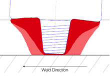
The solid-state nature of the FSW process, combined with its unusual tool shape and asymmetric speed profile, results in a highly characteristic microstructure. The microstructure can be broken up into the following zones:
- The stir zone (also nugget, dynamically recrystallised zone) is a region of heavily deformed material that roughly corresponds to the location of the pin during welding. The grains within the stir zone are roughly equiaxed and often an order of magnitude smaller than the grains in the parent material.[4] A unique feature of the stir zone is the common occurrence of several concentric rings which has been referred to as an "onion-ring" structure.[5] The precise origin of these rings has not been firmly established, although variations in particle number density, grain size and texture have all been suggested.
- The flow arm zone is on the upper surface of the weld and consists of material that is dragged by the shoulder from the retreating side of the weld, around the rear of the tool, and deposited on the advancing side.
- The thermo-mechanically affected zone (TMAZ) occurs on either side of the stir zone. In this region the strain and temperature are lower and the effect of welding on the microstructure is correspondingly smaller. Unlike the stir zone the microstructure is recognizably that of the parent material, albeit significantly deformed and rotated. Although the term TMAZ technically refers to the entire deformed region it is often used to describe any region not already covered by the terms stir zone and flow arm.
- The heat-affected zone (HAZ) is common to all welding processes. As indicated by the name, this region is subjected to a thermal cycle but is not deformed during welding. The temperatures are lower than those in the TMAZ but may still have a significant effect if the microstructure is thermally unstable. In fact, in age-hardened aluminium alloys this region commonly exhibits the poorest mechanical properties.[6]
Advantages and limitations
The solid-state nature of FSW leads to several advantages over fusion welding methods as problems associated with cooling from the liquid phase are avoided. Issues such as porosity, solute redistribution, solidification cracking and liquation cracking do not arise during FSW. In general, FSW has been found to produce a low concentration of defects and is very tolerant of variations in parameters and materials.
Nevertheless, FSW is associated with a number of unique defects, if it isn't done properly. Insufficient weld temperatures, due to low rotational speeds or high traverse speeds, for example, mean that the weld material is unable to accommodate the extensive deformation during welding. This may result in long, tunnel-like defects running along the weld which may occur on the surface or subsurface. Low temperatures may also limit the forging action of the tool and so reduce the continuity of the bond between the material from each side of the weld. The light contact between the material has given rise to the name "kissing-bond". This defect is particularly worrying since it is very difficult to detect using nondestructive methods such as X-ray or ultrasonic testing. If the pin is not long enough or the tool rises out of the plate then the interface at the bottom of the weld may not be disrupted and forged by the tool, resulting in a lack-of-penetration defect. This is essentially a notch in the material which can be a potential source of fatigue cracks.
A number of potential advantages of FSW over conventional fusion-welding processes have been identified:[7]
- Good mechanical properties in the as-welded condition
- Improved safety due to the absence of toxic fumes or the spatter of molten material.
- No consumables — A threaded pin made of conventional tool steel, e.g., hardened H13, can weld over 1 km (0.62 mi) of aluminium, and no filler or gas shield is required for aluminium.
- Easily automated on simple milling machines — lower setup costs and less training.
- Can operate in all positions (horizontal, vertical, etc.), as there is no weld pool.
- Generally good weld appearance and minimal thickness under/over-matching, thus reducing the need for expensive machining after welding.
- Can use thinner materials with same joint strength.
- Low environmental impact.
- General performance and cost benefits from switching from fusion to friction.
However, some disadvantages of the process have been identified:
- Exit hole left when tool is withdrawn.
- Large down forces required with heavy-duty clamping necessary to hold the plates together.
- Less flexible than manual and arc processes (difficulties with thickness variations and non-linear welds).
- Often slower traverse rate than some fusion welding techniques, although this may be offset if fewer welding passes are required.
Important welding parameters
Tool design

The design of the tool[8] is a critical factor as a good tool can improve both the quality of the weld and the maximum possible welding speed.
It is desirable that the tool material be sufficiently strong, tough, and hard wearing at the welding temperature. Further it should have a good oxidation resistance and a low thermal conductivity to minimise heat loss and thermal damage to the machinery further up the drive train. Hot-worked tool steel such as AISI H13 has proven perfectly acceptable for welding aluminium alloys within thickness ranges of 0.5 – 50 mm [9] but more advanced tool materials are necessary for more demanding applications such as highly abrasive metal matrix composites[10] or higher melting point materials such as steel or titanium.
Improvements in tool design have been shown to cause substantial improvements in productivity and quality. TWI has developed tools specifically designed to increase the penetration depth and thus increasing the plate thicknesses that can be successfully welded. An example is the "whorl" design that uses a tapered pin with re-entrant features or a variable pitch thread to improve the downwards flow of material. Additional designs include the Triflute and Trivex series. The Triflute design has a complex system of three tapering, threaded re-entrant flutes that appear to increase material movement around the tool. The Trivex tools use a simpler, non-cylindrical, pin and have been found to reduce the forces acting on the tool during welding.
The majority of tools have a concave shoulder profile which acts as an escape volume for the material displaced by the pin, prevents material from extruding out of the sides of the shoulder and maintains downwards pressure and hence good forging of the material behind the tool. The Triflute tool uses an alternative system with a series of concentric grooves machined into the surface which are intended to produce additional movement of material in the upper layers of the weld.
Widespread commercial applications of friction stir welding process for steels and other hard alloys such as titanium alloys will require the development of cost-effective and durable tools.[11] Material selection, design and cost are important considerations in the search for commercially useful tools for the welding of hard materials. Work is continuing to better understand the effects of tool material's composition, structure, properties and geometry on their performance, durability and cost.[12]
Tool rotation and traverse speeds
There are two tool speeds to be considered in friction-stir welding; how fast the tool rotates and how quickly it traverses along the interface. These two parameters have considerable importance and must be chosen with care to ensure a successful and efficient welding cycle. The relationship between the rotation speed, the welding speed and the heat input during welding is complex but, in general, it can be said that increasing the rotation speed or decreasing the traverse speed will result in a hotter weld. In order to produce a successful weld it is necessary that the material surrounding the tool is hot enough to enable the extensive plastic flow required and minimize the forces acting on the tool. If the material is too cold then voids or other flaws may be present in the stir zone and in extreme cases the tool may break.
Excessively high heat input, on the other hand may be detrimental to the final properties of the weld. Theoretically, this could even result in defects due to the liquation of low-melting-point phases (similar to liquation cracking in fusion welds). These competing demands lead onto the concept of a "processing window": the range of processing parameters viz. tool rotation and traverse speed, that will produce a good quality weld.[13] Within this window the resulting weld will have a sufficiently high heat input to ensure adequate material plasticity but not so high that the weld properties are excessively deteriorated.
Tool tilt and plunge depth
The plunge depth is defined as the depth of the lowest point of the shoulder below the surface of the welded plate and has been found to be a critical parameter for ensuring weld quality.[14] Plunging the shoulder below the plate surface increases the pressure below the tool and helps ensure adequate forging of the material at the rear of the tool. Tilting the tool by 2–4 degrees, such that the rear of the tool is lower than the front, has been found to assist this forging process. The plunge depth needs to be correctly set, both to ensure the necessary downward pressure is achieved and to ensure that the tool fully penetrates the weld. Given the high loads required, the welding machine may deflect and so reduce the plunge depth compared to the nominal setting, which may result in flaws in the weld. On the other hand, an excessive plunge depth may result in the pin rubbing on the backing plate surface or a significant undermatch of the weld thickness compared to the base material. Variable load welders have been developed to automatically compensate for changes in the tool displacement while TWI have demonstrated a roller system that maintains the tool position above the weld plate.
Welding forces
During welding a number of forces will act on the tool:
- A downwards force is necessary to maintain the position of the tool at or below the material surface. Some friction-stir welding machines operate under load control but in many cases the vertical position of the tool is preset and so the load will vary during welding.
- The traverse force acts parallel to the tool motion and is positive in the traverse direction. Since this force arises as a result of the resistance of the material to the motion of the tool it might be expected that this force will decrease as the temperature of the material around the tool is increased.
- The lateral force may act perpendicular to the tool traverse direction and is defined here as positive towards the advancing side of the weld.
- Torque is required to rotate the tool, the amount of which will depend on the down force and friction coefficient (sliding friction) and/or the flow strength of the material in the surrounding region (stiction).
In order to prevent tool fracture and to minimize excessive wear and tear on the tool and associated machinery, the welding cycle is modified so that the forces acting on the tool are as low as possible, and abrupt changes are avoided. In order to find the best combination of welding parameters, it is likely that a compromise must be reached, since the conditions that favour low forces (e.g. high heat input, low travel speeds) may be undesirable from the point of view of productivity and weld properties.
Flow of material
Early work on the mode of material flow around the tool used inserts of a different alloy, which had a different contrast to the normal material when viewed through a microscope, in an effort to determine where material was moved as the tool passed.[15] [16] The data was interpreted as representing a form of in-situ extrusion where the tool, backing plate and cold base material form the "extrusion chamber" through which the hot, plasticised material is forced. In this model the rotation of the tool draws little or no material around the front of the probe instead the material parts in front of the pin and passes down either side. After the material has passed the probe the side pressure exerted by the "die" forces the material back together and consolidation of the join occurs as the rear of the tool shoulder passes overhead and the large down force forges the material.
More recently, an alternative theory has been advanced that advocates considerable material movement in certain locations.[17] This theory holds that some material does rotate around the probe, for at least one rotation, and it is this material movement that produces the "onion-ring" structure in the stir zone. The researchers used a combination of thin copper strip inserts and a "frozen pin" technique, where the tool is rapidly stopped in place. They suggested that material motion occurs by two processes:
- Material on the advancing side of a weld enters into a zone that rotates and advances with the profiled probe. This material was very highly deformed and sloughs off behind the pin to form arc-shaped features when viewed from above (i.e. down the tool axis). It was noted that the copper entered the rotational zone around the pin, where it was broken up into fragments. These fragments were only found in the arc shaped features of material behind the tool.
- The lighter material came from the retreating side in front of the pin and was dragged around to the rear of the tool and filled in the gaps between the arcs of advancing side material. This material did not rotate around the pin and the lower level of deformation resulted in a larger grain size.
The primary advantage of this explanation is that it provides a plausible explanation for the production of the onion-ring structure.
The marker technique for friction stir welding provides data on the initial and final positions of the marker in the welded material. The flow of material is then reconstructed from these positions. Detailed material flow field during friction stir welding can also be calculated from theoretical considerations based on fundamental scientific principles. Material flow calculations are routinely used in numerous engineering applications. Calculation of material flow fields in friction stir welding can be undertaken both using comprehensive numerical simulations[18][19][20] or simple but insightful analytical equations.[21] The comprehensive models for the calculation of material flow fields also provide important information such as geometry of the stir zone and the torque on the tool.[22][23] The numerical simulations have shown the ability to correctly predict the results from marker experiments[20] and the stir zone geometry observed in friction stir welding experiments.[22][24]
Generation and flow of heat
For any welding process it is, in general, desirable to increase the travel speed and minimise the heat input as this will increase productivity and possibly reduce the impact of welding on the mechanical properties of the weld. At the same time it is necessary to ensure that the temperature around the tool is sufficiently high to permit adequate material flow and prevent flaws or tool damage.
When the traverse speed is increased, for a given heat input, there is less time for heat to conduct ahead of the tool and the thermal gradients are larger. At some point the speed will be so high that the material ahead of the tool will be too cold, and the flow stress too high, to permit adequate material movement, resulting in flaws or tool fracture. If the "hot zone" is too large then there is scope to increase the traverse speed and hence productivity.
The welding cycle can be split into several stages during which the heat flow and thermal profile will be different:[25]
- Dwell. The material is preheated by a stationary, rotating tool to achieve a sufficient temperature ahead of the tool to allow the traverse. This period may also include the plunge of the tool into the workpiece.
- Transient heating. When the tool begins to move there will be a transient period where the heat production and temperature around the tool will alter in a complex manner until an essentially steady-state is reached.
- Pseudo steady-state. Although fluctuations in heat generation will occur the thermal field around the tool remains effectively constant, at least on the macroscopic scale.
- Post steady-state. Near the end of the weld heat may "reflect" from the end of the plate leading to additional heating around the tool.
Heat generation during friction-stir welding arises from two main sources: friction at the surface of the tool and the deformation of the material around the tool.[26] The heat generation is often assumed to occur predominantly under the shoulder, due to its greater surface area, and to be equal to the power required to overcome the contact forces between the tool and the workpiece. The contact condition under the shoulder can be described by sliding friction, using a friction coefficient μ and interfacial pressure P, or sticking friction, based on the interfacial shear strength at an appropriate temperature and strain rate. Mathematical approximations for the total heat generated by the tool shoulder Qtotal have been developed using both sliding and sticking friction models:[25]
(Sliding)

(Sticking)

where ω is the angular velocity of the tool, Rshoulder is the radius of the tool shoulder and Rpin that of the pin. Several other equations have been proposed to account for factors such as the pin but the general approach remains the same.
A major difficulty in applying these equations is determining suitable values for the friction coefficient or the interfacial shear stress. The conditions under the tool are both extreme and very difficult to measure. To date, these parameters have been used as "fitting parameters" where the model works back from measured thermal data to obtain a reasonable simulated thermal field. While this approach is useful for creating process models to predict, for example, residual stresses it is less useful for providing insights into the process itself.
Applications
The FSW process is currently patented by TWI in most industrialised countries and licensed for over 183 users. Friction stir welding and its variants friction stir spot welding and friction stir processing are used for the following industrial applications:[27] shipbuilding and offshore,[28] aerospace,[29][30] automotive,[31] rolling stock for railways,[32] general fabrication,[33] robotics, and computers.
Shipbuilding and offshore

Two Scandinavian aluminium extrusion companies were the first to apply FSW commercially to the manufacture of fish freezer panels at Sapa in 1996, as well as deck panels and helicopter landing platforms at Marine Aluminium Aanensen. Marine Aluminium Aanensen subsequently merged with Hydro Aluminium Maritime to become Hydro Marine Aluminium. Some of these freezer panels are now produced by Riftec and Bayards. In 1997 two-dimensional friction stir welds in the hydrodynamically flared bow section of the hull of the ocean viewer vessel The Boss were produced at Research Foundation Institute with the first portable FSW machine. The Super Liner Ogasawara at Mitsui Engineering and Shipbuilding is the largest friction stir welded ship so far. The Sea Fighter of Nichols Bros and the Freedom class Littoral Combat Ships contain prefabricated panels by the FSW fabricators Advanced Technology and Friction Stir Link, Inc. respectively.[34] The Houbei class missile boat has friction stir welded rocket launch containers of China Friction Stir Centre. HMNZS Rotoiti in New Zealand has FSW panels made by Donovans in a converted milling machine.[35][36] Various companies apply FSW to armor plating for amphibious assault ships [37][38]
Aerospace
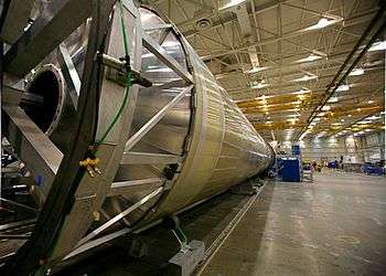
United Launch Alliance applies FSW to the Delta II, Delta IV, and Atlas V expendable launch vehicles, and the first of these with a friction stir welded Interstage module was launched in 1999. The process is also used for the Space Shuttle external tank, for Ares I and for the Orion Crew Vehicle test article at NASA as well as Falcon 1 and Falcon 9 rockets at SpaceX. The toe nails for ramp of Boeing C-17 Globemaster III cargo aircraft by Advanced Joining Technologies[39] and the cargo barrier beams for the Boeing 747 Large Cargo Freighter[39] were the first commercially produced aircraft parts. FAA approved wings and fuselage panels of the Eclipse 500 aircraft were made at Eclipse Aviation, and this company delivered 259 friction stir welded business jets, before they were forced into Chapter 7 liquidation. Floor panels for Airbus A400M military aircraft are now made by Pfalz Flugzeugwerke and Embraer used FSW for the Legacy 450 and 500 Jets [40] Friction stir welding also is employed for fuselage panels on the Airbus A380.[41] BRÖTJE-Automation GmbH uses friction stir welding – through the DeltaN FS® system – for gantry production machines developed for the aerospace sector as well as other industrial applications.[42]
Automotive

Aluminium engine cradles and suspension struts for stretched Lincoln Town Car were the first automotive parts that were friction stir at Tower Automotive, who use the process also for the engine tunnel of the Ford GT. A spin-off of this company is called Friction Stir Link, Inc. and successfully exploits the FSW process, e.g. for the flatbed trailer "Revolution" of Fontaine Trailers.[43] In Japan FSW is applied to suspension struts at Showa Denko and for joining of aluminium sheets to galvanized steel brackets for the boot (trunk) lid of the Mazda MX-5. Friction stir spot welding is successfully used for the bonnet (hood) and rear doors of the Mazda RX-8 and the boot lid of the Toyota Prius. Wheels are friction stir welded at Simmons Wheels, UT Alloy Works and Fundo.[44] Rear seats for the Volvo V70 are friction stir welded at Sapa, HVAC pistons at Halla Climate Control and exhaust gas recirculation coolers at Pierburg. Tailor welded blanks[45] are friction stir welded for the Audi R8 at Riftec.[46] The B-column of the Audi R8 Spider is friction stir welded from two extrusions at Hammerer Aluminium Industries in Austria.
Railways

Since 1997 roof panels were made from aluminium extrusions at Hydro Marine Aluminium with a bespoke 25m long FSW machine, e.g. for DSB class SA-SD trains of Alstom LHB [47] Curved side and roof panels for the Victoria line trains of London Underground, side panels for Bombardier's Electrostar trains[48] at Sapa Group and side panels for Alstom's British Rail Class 390 Pendolino trains are made at Sapa Group[49] Japanese commuter and express A-trains,[50] and British Rail Class 395 trains are friction stir welded by Hitachi,[51] while Kawasaki applies friction stir spot welding to roof panels and Sumitomo Light Metal produces Shinkansen floor panels. Innovative FSW floor panels are made by Hammerer Aluminium Industries in Austria for the Stadler KISS double decker rail cars, to obtain an internal height of 2 m on both floors and for the new car bodies of the Wuppertal Suspension Railway.[52]
Heat sinks for cooling high-power electronics of locomotives are made at Sykatek, EBG, Austerlitz Electronics, EuroComposite, Sapa [53] and Rapid Technic, and are the most common application of FSW due to the excellent heat transfer.
Fabrication
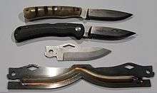
Façade panels and cathode sheets are friction stir welded at AMAG and Hammerer Aluminium Industries including friction stir lap welds of copper to aluminium. Bizerba meat slicers, Ökolüfter HVAC units and Siemens X-ray vacuum vessels are friction stir welded at Riftec. Vacuum valves and vessels are made by FSW at Japanese and Swiss companies. FSW is also used for the encapsulation of nuclear waste at SKB in 50-mm-thick copper canisters.[54][55] Pressure vessels from ø1m semispherical forgings of 38.1mm thick aluminium alloy 2219 at Advanced Joining Technologies and Lawrence Livermore Nat Lab.[56] Friction stir processing is applied to ship propellers at Friction Stir Link, Inc. and to hunting knives by DiamondBlade. Bosch uses it in Worcester for the production of heat exchangers.[57]
Robotics
KUKA Robot Group has adapted its KR500-3MT heavy-duty robot for friction stir welding via the DeltaN FS tool. The system made its first public appearance at the EuroBLECH show in November 2012.[58]
Personal computers
Apple applied friction stir welding on the 2012 iMac to effectively join the bottom to the back of the device.[59]
See also
- Friction welding
- Friction stir processing
- Category:Friction stir welding experts
References
- ↑ Thomas, WM; Nicholas, ED; Needham, JC; Murch, MG;Temple-Smith, P;Dawes, CJ.Friction-stir butt welding, GB Patent No. 9125978.8, International patent application No. PCT/GB92/02203, (1991)
- ↑ Kallee, S.W. (2006-09-06). "Friction Stir Welding at TWI". The Welding Institute (TWI). Retrieved 2009-04-14.
- ↑ Ding, Jeff; Bob Carter; Kirby Lawless; Dr. Arthur Nunes; Carolyn Russell; Michael Suites; Dr. Judy Schneider (2008-02-14). "A Decade of Friction Stir Welding R&D At NASA's Marshall Space Flight Center And a Glance into the Future" (PDF). NASA. Retrieved 2009-04-14.
- ↑ Murr, LE; Liu, G; McClure, JC (1997). "Dynamic recrystallisation in the friction-stir welding of aluminium alloy 1100". Journal of Materials Science Letters. 16 (22): 1801–1803. doi:10.1023/A:1018556332357.
- ↑ Krishnan, K. N. (2002). "On the Formation of Onion Rings in Friction Stir Welds". Materials Science and Engineering A. 327 (2): 246–251. doi:10.1016/S0921-5093(01)01474-5.
- ↑ Mahoney, M. W.; Rhodes, C. G.; Flintoff, J. G.; Bingel, W. H.; Spurling, R. A. (1998). "Properties of Friction-stir-welded 7075 T651 Aluminum". Metallurgical and Materials Transactions A. 29 (7): 1955–1964. doi:10.1007/s11661-998-0021-5.
- ↑ Nicholas, ED (1998). "Developments in the friction-stir welding of metals". ICAA-6: 6th International Conference on Aluminium Alloys. Toyohashi, Japan.
- ↑ By Rajiv S. Mishra, Murray W. Mahoney: Friction stir welding and processing, ASM International ISBN 978-0-87170-848-9.
- ↑ Prado, RA; Murr, LE; Shindo, DJ; Soto, HF (2001). "Tool wear in the friction stir welding of aluminium alloy 6061+20% Al2O3: A preliminary study". Scripta Materialia. 45: 75–80. doi:10.1016/S1359-6462(01)00994-0.
- ↑ Nelson, T; Zhang, H; Haynes, T (2000). "friction stir welding of Al MMC 6061-B4C". 2nd International Symposium on FSW (CD ROM). Gothenburg, Sweden.
- ↑ Bhadeshia HKDH; DebRoy T (2009). "Critical assessment: friction stir welding of steels". Science and Technology of Welding and Joining. 14 (3): 193–196. doi:10.1179/136217109X421300.
- ↑ Rai R; De A; Bhadeshia HKDH; DebRoy T (2011). "Review: friction stir welding tools". Science and Technology of Welding and Joining. 16 (4): 325–342. doi:10.1179/1362171811Y.0000000023.
- ↑ "A flow-partitioned deformation zone model for defect formation during friction stir welding". Scripta Materialia. 58: 372–376. doi:10.1016/j.scriptamat.2007.10.031.
- ↑ Leonard, AJ (2000). "Microstructure and aging behaviour of FSW in Al alloys 2014A-T651 and 7075-T651". 2nd International Symposium on FSW (CD ROM). Gothenburg, Sweden.
- ↑ Reynolds, AP (2000). "Visualisation of material flow in autogenous friction stir welds". Science and technology of welding and joining. 5 (2): 120–124. doi:10.1179/136217100101538119.
- ↑ Seidel, TU; Reynolds, AP (2001). "Visualization of the Material Flow in AA2195 Friction-Stir Welds Using a Marker Insert Technique". Metallurgical and Material Transactions. 32A (11): 2879–2884.
- ↑ Guerra, M; Schmidt, C; McClure, JC; Murr, LE; Nunes, AC (2003). "Flow patterns during friction stir welding". Materials Characterisation. 49 (2): 95–101. doi:10.1016/S1044-5803(02)00362-5.
- ↑ Nandan R; DebRoy T; Bhadeshia HKDH (2008). "Recent advances in friction-stir welding – Process, weldment structure and properties". Progress in Materials Science. 53 (6): 980–1023. doi:10.1016/j.pmatsci.2008.05.001.
- ↑ Nandan R, Roy GG, Lienert TJ, DebRoy T (2007). "Three-dimensional heat and material flow during friction stir welding of mild steel". Acta Materialia. 55 (3): 883–895. doi:10.1016/j.actamat.2006.09.009.
- 1 2 Seidel TU, Reynolds AP (2003). "Two-dimensional friction stir welding process model based on fluid mechanics". Science and Technology of Welding and Joining. 8 (3): 175–183. doi:10.1179/136217103225010952.
- ↑ Arora A; DebRoy T; Bhadeshia HKDH (2011). "Back-of-the-envelope calculations in friction stir welding – Velocities, peak temperature, torque, and hardness". Acta Materialia. 59 (5): 2020–2028. doi:10.1016/j.actamat.2010.12.001.
- 1 2 Arora A, Nandan R, Reynolds AP, DebRoy T (2009). "Torque, power requirement and stir zone geometry in friction stir welding through modeling and experiments". Scripta Materialia. 60 (1): 13–16. doi:10.1016/j.scriptamat.2008.08.015.
- ↑ Mehta M, Arora A, De A, DebRoy T (2011). "Tool Geometry for Friction Stir Welding—Optimum Shoulder Diameter". Metallurgical and Materials Transactions A. 42 (9): 2716–2722. doi:10.1007/s11661-011-0672-5.
- ↑ Nandan R, Roy GG, DebRoy T (2011). "Numerical simulation of three-dimensional heat transfer and plastic flow during friction stir welding". Metallurgical and Materials Transactions A. 37 (4): 1247–1259. doi:10.1007/s11661-006-1076-9.
- 1 2 Frigaard, O; Grong, O; Midling, O T (2001). "A process model for friction-stir welding of age hardening aluminium alloys". Metallurgical and Material Transactions. 32A (5): 1189–1200. doi:10.1007/s11661-001-0128-4.
- ↑ Qi, X, Chao, Y J (1999). "Heat transfer and Thermo-Mechanical analysis of FSW joining of 6061-T6 plates". 1st International Symposium on FSW (CD ROM). Thousand Oaks, USA: TWI.
- ↑ D. Lohwasser and Z. Chen: "Friction stir welding — From basics to applications" Woodhead Publishing 2010, Chapter 5, Pages 118–163, ISBN 978-1-84569-450-0.
- ↑ Fred Delany, Stephan W Kallee, Mike J Russell: "Friction stir welding of aluminium ships", Paper presented at 2007 International Forum on Welding Technologies in the Shipping Industry (IFWT). Held in conjunction with the Beijing Essen Welding and Cutting Fair in Shanghai, 16–19 June 2007.
- ↑ Video: ''FSW at British Aerospace''. Twi.co.uk. Retrieved on 2012-01-03.
- ↑ Video: FSW of aerospace fuselages. Twi.co.uk. Retrieved on 2012-01-03.
- ↑ S. W. Kallee, J. M. Kell, W. M. Thomas und C. S. Wiesner:"Development and implementation of innovative joining processes in the automotive industry", Paper presented at DVS Annual Welding Conference "Große Schweißtechnische Tagung", Essen, Germany, 12–14 September 2005.
- ↑ S. W. Kallee and J. Davenport: "Trends in the design and fabrication of rolling stock", Paper published in European Railway Review, Volume 13, Issue 1, 2007.
- ↑ Mike Page: "Friction stir welding broadens applications base", Report of a EuroStir meeting, 3 Sept 2003.
- ↑ Bill Arbegast, Tony Reynolds, Rajiv S. Mishra, Tracy Nelson, Dwight Burford: Littoral Combat System with Improved Welding Technologies, Center for Friction STIR Processing (CFSP).
- ↑ Richard Worrall: "Welded Bliss", e.nz magazine March/April 2008.
- ↑ Stephan Kallee: "NZ Fabricators begin to use Friction Stir Welding to produce aluminium components and panels", Paper published in New Zealand Engineering News, August 2006.
- ↑ Friction Stir Welding Demonstrated for Combat Vehicle Construction ... for 2519 aluminium armor for the U.S. Marine Corps' Advanced Amphibious Assault Vehicle, Welding Journal 03 2003.
- ↑ G Campbell and T Stotler: Friction Stir Welding of Armor Grade Aluminum Plate , Welding Journal, Dec 1999.
- 1 2 Walter Polt "A little friction at Boeing", Boeing Frontiers Online, September 2004, Vol. 3, Issue 5
- ↑ Embraer Performs First Metal Cut for Legacy 500 Jet, BART International.
- ↑ "How Airbus uses friction stir welding". Reliable Plant. Retrieved 7 August 2013.
- ↑ "JEC Composites Show – Day 3: EADS licenses its patented DeltaN friction-stir welding technology to BRÖTJE-Automation". EADS. Retrieved 30 July 2013.
- ↑ A Revolution makes a lot of difference. fontainetrailer.com
- ↑ Fundo's FSW Wheels provide improved performance and reduced running costs. twi.co.uk/
- ↑ FSW used in automotive tailor welded blanks. Twi.co.uk. Retrieved on 2012-01-03.
- ↑ FSW applications at Riftec, riftec.de.
- ↑ S.W. Kallee, J. Davenport and E.D. Nicholas: "Railway Manufacturers Implement Friction Stir Welding", Welding Journal, October 2002.
- ↑ Video: ''Friction stir welding of Bombardier trains'', archived from the original on 27 September 2011. Twi.co.uk.
- ↑ Sapa's Capabilities, Long length FSW — Max. length 26 m — Max. width 3,5 m — Double sided welding, Sapa company brochure.
- ↑ History, Principles and Advantages of FSW on Hitachi Transportation Systems Website. Hitachi-rail.com. Retrieved on 2012-01-03.
- ↑ Hitachi Class 395 Railway Strategies Live 2010. 23 June 2010, pp. 12–13. (PDF) . Retrieved on 2012-01-03.
- ↑ F. Ellermann, S. Pommer, G. Barth: Einsatz des Rührreibschweißens bei der Fertigung der Wagenkästen für die Schwebebahn Wuppertal. DVS Congress: Große Schweißtechnische Tagung, 15./16. September, Hotel Pullman Berlin Schweizerhof, Berlin.
- ↑ FSW: Increased strength, Improved leakproofness, Improved repeatability. Reduced heat distortion, Sapa company brochure.
- ↑ Video: ''Electron Beam Welding and Friction Stir Welding of Copper Canisters''. Twi.co.uk. Retrieved on 2012-01-03.
- ↑ Nielsen, Isak (2012). Modeling and Control of Friction Stir Welding in 5 cm (2 in) thick Copper Canisters (M.Sc. thesis). Linköping University.
- ↑ E Dalder, J W Pasternak, J Engel, R S Forrest, E Kokko, K McTernan and D Waldron Friction stir welding of thick walled alumnium pressure vessels, Welding Journal, April 2008, pp. 40–44.
- ↑ YouTube Video.
- ↑ "Partnership success with EADS' DeltaN FS® friction-stir welding technology for industrial robots". EADS. Retrieved 30 July 2013.
- ↑ "Apple unveils totally redesigned 27 and 21.5 imac". TechCrunch.
External links
- Friction stir welding at TWI
- Friction-stir welding research at University of Cambridge
- Friction-stir welding of aluminum alloy to steel; academic article from the 2004 Welding Journal
- Friction stir welding research at Vanderbilt University Welding Automation Laboratory
- Back of the envelope calculations in friction stir welding
- Theory of materials processing/welding research group at Penn State University
- Friction Stir Welding Machines: Applications & Key Features