Fresnel zone
A Fresnel zone (/freɪˈnɛl/ fray-NEL), named for physicist Augustin-Jean Fresnel, is a series of concentric ellipsoidal regions of alternating double strength and half strength volumes of a wave's propagation, caused by a wave following multiple paths as it passes by an object and is partially refracted by it, resulting in constructive and destructive interference as the different length paths go in and out of phase.
Fresnel zones are seen in optics, radio communications, electrodynamics, seismology, acoustics, gravitational radiation, and other situations involving the radiation of waves and multipath propagation. Fresnel zone computations are used to anticipate obstacle clearances required when designing highly directive systems such as microwave parabolic antenna systems.
This is the cause of the picket-fencing effect when either the radio transmitter or receiver is moving and the high and low signal strength zones are above and below the receiver cut off threshold.
Importance of Fresnel zones
Fresnel zones are concentric ellipses (1, 2, 3) centred on the direct transmission path (AB).

The 1st zone is the ellipse with chords 1/2 wavelength longer than the direct path (ACB).
If a reflective object is very near the direct path, the signal will experience a 180o phase shift and cancel the direct wave at the receiver.
If a reflective object is tangent to the 1st zone, the electromagnetic wave will be shifted 180o because of the increased path length, undergo an additional 180o phase shift due to the reflection, and reinforce the direct wave at the receiver. Consequently, there should be no reflective objects in the 1st Fresnel zone.
If unobstructed, radio waves will travel in a straight line from the transmitter to the receiver. But if there are reflective surfaces along the path, such as bodies of water or smooth terrain, the radio waves reflecting off those surfaces may arrive either out of phase or in phase with the signals that travel directly to the receiver. Waves that reflect off surfaces within an odd Fresnel zone are out of phase with the direct-path wave and reduce the power of the received signal. Waves that reflect off surfaces within an even Fresnel zone are in phase with the direct-path wave and can enhance the power of the received signal. Sometimes this results in the counter-intuitive finding that reducing the height of an antenna increases the signal-to-noise ratio. (This conflicts with many sources, which state that the direct path is zone 1; therefore, obstructing odd-numbered zones can have a constructive effect and vice-versa. For example, obstructing zone 2 would deflect some of it into the direct zone 1, thus adding destructively and weakening the signal.)
Fresnel provided a means to calculate where the zones are—where a given obstacle will cause mostly in phase or mostly out of phase reflections between the transmitter and the receiver. Obstacles in the first Fresnel zone will create signals with a path-length phase shift of 0 to 180 degrees, in the second zone they will be 180 to 360 degrees out of phase, and so on. Even numbered zones have the maximum phase cancelling effect and odd numbered zones may actually add to the signal power.[1]
To maximize receiver strength, one needs to minimize the effect of obstruction loss by removing obstacles from the radio frequency line of sight (RF LoS). The strongest signals are on the direct line between transmitter and receiver and always lie in the first Fresnel zone.
Determining Fresnel zone clearance

The concept of Fresnel zone clearance may be used to analyze interference by obstacles near the path of a radio beam. The first zone must be kept largely free from obstructions to avoid interfering with the radio reception. However, some obstruction of the Fresnel zones can often be tolerated. As a rule of thumb the maximum obstruction allowable is 40%, but the recommended obstruction is 20% or less.
For establishing Fresnel zones, first determine the RF Line of Sight (RF LoS), which in simple terms is a straight line between the transmitting and receiving antennas. Now the zone surrounding the RF LoS is said to be the Fresnel zone.[2]
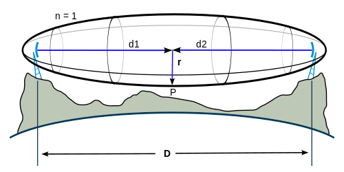
The general equation for calculating the Fresnel zone radius at any point P in between the endpoints of the link is the following:

where
- is the th Fresnel Zone radius,
- is the distance of P from one end,
- is the distance of P from the other end,
- is the wavelength of the transmitted signal.


The cross sectional radius of each Fresnel zone is the longest at the midpoint of the RF LoS, shrinking to a point at the antenna on each end. For practical applications, it is often useful to know the maximum radius of the first Fresnel zone. Using , , and in the above formula gives


where
- is the distance between the two antennas,
- is the frequency of the transmitted signal,
- ≈ 2.997×10⁸ m/s is the speed of light in the air.


Substitution of the numeric value for followed by a unit conversion results in an easy way to calculate the radius of the first Fresnel zone , knowing the distance between the two antennas and the frequency of the transmitted signal :

![{\displaystyle F_{1}\mathrm {[m]} =8.656{\sqrt {D\mathrm {[km]} \over f\mathrm {[GHz]} }}}](../I/m/ccf7bd68f1b0f627e590302216048c7af942b6dc.svg)
![{\displaystyle F_{1}\mathrm {[ft]} =36.03{\sqrt {D\mathrm {[mi]} \over f\mathrm {[GHz]} }}}](../I/m/3d215dd6723ea1ba4562eaafa55ff21b6755fd01.svg)
See also
References
- ↑ "Wireless – Fresnel Zones and their Effect". zytrax.com. Retrieved 2008-02-21.
- ↑ "Fresnel Zone Clearance". softwright.com. Retrieved 2008-02-21.
- ↑ Tomasi, Wayne. Electronic Communication Systems - Fundamentals Through Advanced. Pearson. p. 1023.
 This article incorporates public domain material from the General Services Administration document "Federal Standard 1037C" (in support of MIL-STD-188).
External links
- Generate 3D Fresnel zone, as a Google Earth KML file
- Fresnel Zone Calculator and Elevation Chart
- Fresnel Zone Calculator
- FEN Fresnel Zone Calculator
- More Fresnel Zone Details
- R.E. Sherriff, Understanding the Fresnel zone
- VHF/UHF/Microwave Radio Propagation: A Primer for Digital Experimenters