Fluidyne engine

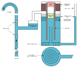
A Fluidyne engine is an alpha or gamma type Stirling engine with one or more liquid pistons. It contains a working gas (often air), and either two liquid pistons or one liquid piston and a displacer.
The engine was invented in 1969.[1] The enigne was patented 1973 by the Automatic Engergy Authority UK.[2][1]
Engine operation
Working gas in the engine is heated, and this causes it to expand and push on the water column. This expansion cools the air which contracts, at the same time being pushed back by the weight of the displaced water column. The cycle then repeats.
Engine as a pump
In the classic configuration, the work produced via the water pistons is integrated with a water pump. The simple pump is external to the engine, and consists of two check valves, one on the intake and one on the outlet. In the engine, the loop of oscillating liquid can be thought of as acting as a displacer piston. The liquid in the single tube extending to the pump acts as the power piston. Traditionally the pump is open to the atmosphere, and the hydraulic head is small, so that the absolute engine pressure is close to atmospheric pressure.[1][3][4]
Demonstration video


The videos show operation of a model Fluidyne engine. Hot pipe is heated by a heat gun, and water column oscillation builds up to a steady-state level. Second video shows a detail of the actual water displacement. Fluidyne pumps are commercially available.
See also
References
- 1 2 3 West, C. D. (August 1987). "Stirling Engines, and Irrigation Pumping" (PDF). Oak Ridge National Laboratory. Retrieved August 6, 2011.
This report was prepared in support of the Renewable Energy Applications and Training Project that is sponsored by the U.S. Agency for International Development for which ORNL provides technical assistance. It briefly outlines the performance that might be achievable from various kinds of Stirling-engine-driven irrigation pumps. Some emphasis is placed on the very simple liquid-piston engines that have been the subject of research in recent years and are suitable for manufacture in less well-developed countries. In addition to the results quoted here (possible limits on M4 and pumping head for different-size engines and various operating conditions), the method of calculation is described in sufficient detail for engineers to apply the techniques to other Stirling engine designs for comparison.
- ↑ GB1329567 (A) - STIRLING CYCLE HEAT ENGINES
- ↑ West, C. D. (1983). Liquid piston Stirling engines. New York: Van Nostrand Reinhold. p. 7. ISBN 978-0-442-29237-9.
- ↑ Swift, G. (1999). Thermoacoustics: A unifying perspective for some engines and refrigerators. p. 300. ISBN 978-0-735-40065-8.
Further reading
- Colin West (1974-08-09). "And Yet It Moves". New Scientist. 63 (912): 530–531. ISSN 0262-4079.
External links
| Wikimedia Commons has media related to Fluidynes. |