Faraday paradox
The Faraday paradox or Faraday's paradox is any experiment in which Michael Faraday's law of electromagnetic induction appears to predict an incorrect result. The paradoxes fall into two classes:
- Faraday's law appears to predict that there will be zero EMF but there is a non-zero EMF.
- Faraday's law appears to predict that there will be a non-zero EMF but there is a zero EMF.
Faraday deduced his law of induction in 1831, after inventing the first electromagnetic generator or dynamo, but was never satisfied with his own explanation of the paradox.
Faraday's law compared to the Maxwell–Faraday equation
Faraday's law (also known as the Faraday–Lenz law) states that the electromotive force (EMF) is given by the total derivative of the magnetic flux with respect to time t:

where is the EMF and ΦB is the magnetic flux. The direction of the electromotive force is given by Lenz's law. An often overlooked fact is that Faraday's law is based on the total derivative, not the partial derivative, of the magnetic flux. This means that an EMF may be generated even if total flux through the surface is constant. To overcome this issue, special techniques may be used. See below for the section on Use of special techniques with Faraday's law. However, the most common interpretation of Faraday's law is that:

The induced electromotive force in any closed circuit is equal to the negative of the time rate of change of the magnetic flux enclosed by the circuit.[1][2]
This version of Faraday's law strictly holds only when the closed circuit is a loop of infinitely thin wire,[3] and is invalid in other circumstances. It ignores the fact that Faraday's law is defined by the total, not partial, derivative of magnetic flux and also the fact that EMF is not necessarily confined to a closed path but may also have radial components as discussed below. A different version, the Maxwell–Faraday equation (discussed below), is valid in all circumstances, and when used in conjunction with the Lorentz force law it is consistent with correct application of Faraday's law.
Outline of proof of Faraday's law from Maxwell's equations and the Lorentz force law. Consider the time-derivative of flux through a possibly moving loop, with area : The integral can change over time for two reasons: The integrand can change, or the integration region can change. These add linearly, therefore:
where t0 is any given fixed time. We will show that the first term on the right-hand side corresponds to transformer EMF, the second to motional EMF. The first term on the right-hand side can be rewritten using the integral form of the Maxwell–Faraday equation:
 Area swept out by vector element dℓ of curve ∂Σ in time dt when moving with velocity v.
Next, we analyze the second term on the right-hand side:
This is the most difficult part of the proof; more details and alternate approaches can be found in references.[4][5][6] As the loop moves and/or deforms, it sweeps out a surface (see figure on right). The magnetic flux through this swept-out surface corresponds to the magnetic flux that is either entering or exiting the loop, and therefore this is the magnetic flux that contributes to the time-derivative. (This step implicitly uses Gauss's law for magnetism: Since the flux lines have no beginning or end, they can only get into the loop by getting cut through by the wire.) As a small part of the loop moves with velocity v for a short time , it sweeps out a vector area vector . Therefore, the change in magnetic flux through the loop here is
Therefore:
where v is the velocity of a point on the loop .
Putting these together,
Meanwhile, EMF is defined as the energy available per unit charge that travels once around the wire loop. Therefore, by the Lorentz force law,
Combining these,


The Maxwell–Faraday equation is a generalisation of Faraday's law that states that a time-varying magnetic field is always accompanied by a spatially-varying, non-conservative electric field, and vice versa. The Maxwell–Faraday equation is:

(in SI units) where is the partial derivative operator, is the curl operator and again E(r, t) is the electric field and B(r, t) is the magnetic field. These fields can generally be functions of position r and time t.


The Maxwell–Faraday equation is one of the four Maxwell's equations, and therefore plays a fundamental role in the theory of classical electromagnetism. It can also be written in an integral form by the Kelvin–Stokes theorem.[7]
Paradoxes in which Faraday's law of induction seems to predict zero EMF but actually predicts non-zero EMF
These paradoxes are generally resolved by the fact that an EMF may be created by a changing flux in a circuit as explained in Faraday's law or by the movement of a conductor in a magnetic field. This is explained by Feynman as noted below. See also A. Sommerfeld, Vol III Electrodynamics Academic Press, page 362.
The equipment

The experiment requires a few simple components (see Figure 1): a cylindrical magnet, a conducting disc with a conducting rim, a conducting axle, some wiring, and a galvanometer. The disc and the magnet are fitted a short distance apart on the axle, on which they are free to rotate about their own axes of symmetry. An electrical circuit is formed by connecting sliding contacts: one to the axle of the disc, the other to its rim. A galvanometer can be inserted in the circuit to measure the current.
The procedure
The experiment proceeds in three steps:
- The magnet is held to prevent it from rotating, while the disc is spun on its axis. The result is that the galvanometer registers a direct current. The apparatus therefore acts as a generator, variously called the Faraday generator, the Faraday disc, or the homopolar (or unipolar) generator.
- The disc is held stationary while the magnet is spun on its axis. The result is that the galvanometer registers no current.
- The disc and magnet are spun together. The galvanometer registers a current, as it did in step 1.
Why is this paradoxical?
The experiment is described by some as a "paradox" as it seems, at first sight, to violate Faraday's law of electromagnetic induction, because the flux through the disc appears to be the same no matter what is rotating. Hence, the EMF is predicted to be zero in all three cases of rotation. The discussion below shows this viewpoint stems from an incorrect choice of surface over which to calculate the flux.
The paradox appears a bit different from the lines of flux viewpoint: in Faraday's model of electromagnetic induction, a magnetic field consisted of imaginary lines of magnetic flux, similar to the lines that appear when iron filings are sprinkled on paper and held near a magnet. The EMF is proposed to be proportional to the rate of cutting lines of flux. If the lines of flux are imagined to originate in the magnet, then they would be stationary in the frame of the magnet, and rotating the disc relative to the magnet, whether by rotating the magnet or the disc, should produce an EMF, but rotating both of them together should not.
Faraday's explanation
In Faraday's model of electromagnetic induction, a circuit received an induced current when it cut lines of magnetic flux. According to this model, the Faraday disc should have worked when either the disc or the magnet was rotated, but not both. Faraday attempted to explain the disagreement with observation by assuming that the magnet's field, complete with its lines of flux, remained stationary as the magnet rotated (a completely accurate picture, but maybe not intuitive in the lines-of-flux model). In other words, the lines of flux have their own frame of reference. As we shall see in the next section, modern physics (since the discovery of the electron) does not need the lines-of-flux picture and dispels the paradox.
Modern explanations
Taking the return path into account
In step 2, since there is no current observed, one might conclude that the magnetic field did not rotate with the rotating magnet. (Whether it does or does not effectively or relatively, the Lorentz force is zero since v is zero relative to the laboratory frame. So there is no current measuring from laboratory frame.) The use of the Lorentz equation to explain this paradox has led to a debate in the literature as to whether or not a magnetic field rotates with a magnet. Since the force on charges expressed by the Lorentz equation depends upon the relative motion of the magnetic field (i.e. the laboratory frame) to the conductor where the EMF is located it was speculated that in the case when the magnet rotates with the disk but a voltage still develops, the magnetic field (i.e. the laboratory frame) must therefore not rotate with the magnetic material (of course since it is the laboratory frame), while the effective definition of magnetic field frame or the "effective/relative rotation of the field" turns with no relative motion with respect to the conductive disk.
Careful thought showed that, if the magnetic field was assumed to rotate with the magnet and the magnet rotated with the disk, a current should still be produced, not by EMF in the disk (there is no relative motion between the disk and the magnet) but in the external circuit linking the brushes,[8] which is in fact in relative motion with respect to the rotating magnet. (The brushes are in the laboratory frame.)
This mechanism agrees with the observations involving return paths: an EMF is generated whenever the disc moves relative to the return path, regardless of the rotation of the magnet. In fact it was shown that so long as a current loop is used to measure induced EMFs from the motion of the disk and magnet it is not possible to tell if the magnetic field does or does not rotate with the magnet. (This depends on the definition, the motion of a field can be only defined effectively/relatively. If you hold the view that the field flux is a physical entity, it does rotate or depends on how it is generated. But this does not alter what is used in the Lorentz formula, especially the v, the velocity of the charge carrier relative to the frame where measurement takes place and field strength varies according to relativity at any spacetime point.)
Several experiments have been proposed using electrostatic measurements or electron beams to resolve the issue, but apparently none have been successfully performed to date.
Using the Lorentz force
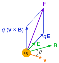
The force F acting on a particle of electric charge q with instantaneous velocity v, due to an external electric field E and magnetic field B, is given by the Lorentz force:[9]

where × is the vector cross product. All boldface quantities are vectors. The relativistically-correct electric field of a point charge varies with velocity as:[10]

where is the unit vector pointing from the current (non-retarded) position of the particle to the point at which the field is being measured, and θ is the angle between and . The magnetic field B of a charge is:[10]


At the most underlying level, the total Lorentz force is the cumulative result of the electric fields E and magnetic fields B of every charge acting on every other charge.
When the magnet is rotating, but flux lines are stationary, and the conductor is stationary
Consider the special case where the cylindrical conducting disk is stationary but the cylindrical magnetic disk is rotating. In such a situation, the mean velocity v of charges in the conducting disk is initially zero, and therefore the magnetic force F = qv × B is 0, where v is the mean velocity of a charge q of the circuit relative to the frame where measurements are taken, and q is the charge on an electron.
Note that v does not represent the velocity that magnetic fields lines travel through the conductor. The magnetic field pattern observed depends on the frame of reference. They have no velocity on their own. To illustrate, imagine that one were to take a magnet and flip it 180 degrees. The result of assuming that these field lines actually have velocity of their own would be that magnetic field lines far away would swing to the other side, potentially faster than the speed of light, however, that is not what happens.
Instead, what happens is that rotating a magnet causes subatomic particles in the magnet to acquire a change in velocity. However, in the rotated magnet, the velocities of electrons would vary ahead or behind those of the other particles, due to their lower mass compared to nuclei. There is length contraction of fields propagating from moving charges, and the length contraction of the electric fields E of the electrons would be greater or lesser than the contraction of the E fields of the positive nuclei depending on whether the rotation of the magnet was aligned to, or opposed to, the electron spins which give rise to the magnetism.
In the case of an axially-symmetric magnet spinning at constant velocity, the distribution of the magnetic field intensity B of the magnet is constant with time, even after accounting for the relativistic corrections to B, and therefore by the Maxwell–Faraday equation the electric field induced by the rotation of the magnet is curl-free, which is caused purely by length contraction of the electric fields of its constituting subatomic particles. This means that in this particular example with a rotating magnetic disk and a stationary conducting disk, the induced electric field cannot be described by the Maxwell–Faraday equation, which describes the curl of the electric field induced by a changing magnetic flux density.
Therefore, in this view, magnetic fields do not rotate with their magnetic source, and they exist independently of them. Nevertheless, the Lorentz forces generated by the rotation of the magnet are as if these lines rotated in unison with it, but this is in reality due to the effect of relativity on electric fields.
When the magnet and the flux lines are stationary and the conductor is rotating
After the discovery of the electron and the forces that affect it, a microscopic resolution of the paradox became possible. See Figure 1. The metal portions of the apparatus are conducting, and confine a current due to electronic motion to within the metal boundaries. All electrons that move in a magnetic field experience a Lorentz force of F = qv × B, where v is the velocity of the electrons relative to the frame where measurements are taken, and q is the charge on an electron. Remember, there is no such frame as "frame of the electromagnetic field". A frame is set on a specific spacetime point, not an extending field or a flux line as a mathematical object. It is a different issue if you consider flux as a physical entity (see Magnetic flux quantum), or consider the effective/relative definition of motion/rotation of a field (see below). This note helps resolve the paradox.
The Lorentz force is perpendicular to both the velocity of the electrons, which is in the plane of the disc, and to the magnetic field, which is normal (surface normal) to the disc. An electron at rest in the frame of the disc moves circularly with the disc relative to the B-field (i.e. the rotational axis or the laboratory frame, remember the note above), and so experiences a radial Lorentz force. In Figure 1 this force (on a positive charge, not an electron) is outward toward the rim according to the right-hand rule.
Of course, this radial force, which is the cause of the current, creates a radial component of electron velocity, generating in turn its own Lorentz force component that opposes the circular motion of the electrons, tending to slow the disc's rotation, but the electrons retain a component of circular motion that continues to drive the current via the radial Lorentz force.
Use of special techniques with Faraday's law
The flux through the portion of the path from the brush at the rim, through the outside loop and the axle to the center of the disc is always zero because the magnetic field is in the plane of this path (not perpendicular to it), no matter what is rotating, so the integrated emf around this part of the path is always zero. Therefore, attention is focused on the portion of the path from the axle across the disc to the brush at the rim.
Faraday's law of induction can be stated in words as:[11]
The induced electromotive force or EMF in any closed circuit is equal to the time rate of change of the magnetic flux through the circuit.
Mathematically, the law is stated:

where ΦB is the flux, and dA is a vector element of area of a moving surface Σ(t) bounded by the loop around which the EMF is to be found.

How can this law be connected to the Faraday disc generator, where the flux linkage appears to be just the B-field multiplied by the area of the disc?
One approach is to define the notion of "rate of change of flux linkage" by drawing a hypothetical line across the disc from the brush to the axle and asking how much flux linkage is swept past this line per unit time. See Figure 2. Assuming a radius R for the disc, a sector of disc with central angle θ has an area:

so the rate that flux sweeps past the imaginary line is

with ω = dθ / dt the angular rate of rotation. The sign is chosen based upon Lenz's law: the field generated by the motion must oppose the change in flux caused by the rotation. For example, the circuit with the radial segment in Figure 2 according to the right-hand rule adds to the applied B-field, tending to increase the flux linkage. That suggests that the flux through this path is decreasing due to the rotation, so dθ / dt is negative.
This flux-cutting result for EMF can be compared to calculating the work done per unit charge making an infinitesimal test charge traverse the hypothetical line using the Lorentz force / unit charge at radius r, namely | v × B | = Bv = Brω:

which is the same result.
The above methodology for finding the flux cut by the circuit is formalized in the flux law by properly treating the time derivative of the bounding surface Σ(t). Of course, the time derivative of an integral with time dependent limits is not simply the time derivative of the integrand alone, a point often forgotten; see Leibniz integral rule and Lorentz force.
In choosing the surface Σ(t), the restrictions are that (i) it has to be bounded by a closed curve around which the EMF is to be found, and (ii) it has to capture the relative motion of all moving parts of the circuit. It is emphatically not required that the bounding curve corresponds to a physical line of flow of the current. On the other hand, induction is all about relative motion, and the path emphatically must capture any relative motion. In a case like Figure 1 where a portion of the current path is distributed over a region in space, the EMF driving the current can be found using a variety of paths. Figure 2 shows two possibilities. All paths include the obvious return loop, but in the disc two paths are shown: one is a geometrically simple path, the other a tortuous one. We are free to choose whatever path we like, but a portion of any acceptable path is fixed in the disc itself and turns with the disc. The flux is calculated though the entire path, return loop plus disc segment, and its rate-of change found.

In this example, all these paths lead to the same rate of change of flux, and hence the same EMF. To provide some intuition about this path independence, in Figure 3 the Faraday disc is unwrapped onto a strip, making it resemble a sliding rectangle problem. In the sliding rectangle case, it becomes obvious that the pattern of current flow inside the rectangle is time-independent and therefore irrelevant to the rate of change of flux linking the circuit. There is no need to consider exactly how the current traverses the rectangle (or the disc). Any choice of path connecting the top and bottom of the rectangle (axle-to-brush in the disc) and moving with the rectangle (rotating with the disc) sweeps out the same rate-of-change of flux, and predicts the same EMF. For the disc, this rate-of-change of flux estimation is the same as that done above based upon rotation of the disc past a line joining the brush to the axle.
Configuration with a return path
Whether the magnet is "moving" is irrelevant in this analysis, due the flux induced in the return path. The crucial relative motion is that of the disk and the return path, not of the disk and the magnet. This becomes clearer if a modified Faraday disk is used in which the return path is not a wire but another disk. That is, mount two conducting disks just next to each other on the same axle and let them have sliding electrical contact at the center and at the circumference. The current will be proportional to the relative rotation of the two disks and independent of any rotation of the magnet.
Configuration without a return path
A Faraday disk can also be operated with neither a galvanometer nor a return path. When the disk spins, the electrons collect along the rim and leave a deficit near the axis (or the other way around). It is possible in principle to measure the distribution of charge, for example, through the electromotive force generated between the rim and the axle (though not necessarily easy). This charge separation will be proportional to the relative rotational velocity between the disk and the magnet.
Paradoxes in which Faraday's law of induction seems to predict non-zero EMF but actually predicts zero EMF
These paradoxes are generally resolved by determining that the apparent motion of the circuit is actually deconstruction of the circuit followed by reconstruction of the circuit on a different path.
An additional rule

In the case when the disk alone spins there is no change in flux through the circuit, however, there is an electromotive force induced contrary to Faraday's law. We can also show an example when there is a change in flux, but no induced voltage. Figure 5 (near right) shows the setup used in Tilley's experiment.[12] It is a circuit with two loops or meshes. There is a galvanometer connected in the right-hand loop, a magnet in the center of the left-hand loop, a switch in the left-hand loop, and a switch between the loops. We start with the switch on the left open and that on the right closed. When the switch on the left is closed and the switch on the right is open there is no change in the field of the magnet, but there is a change in the area of the galvanometer circuit. This means that there is a change in flux. However the galvanometer did not deflect meaning there was no induced voltage, and Faraday's law does not work in this case. According to A. G. Kelly this suggests that an induced voltage in Faraday's experiment is due to the "cutting" of the circuit by the flux lines, and not by "flux linking" or the actual change in flux. This follows from the Tilley experiment because there is no movement of the lines of force across the circuit and therefore no current induced although there is a change in flux through the circuit. Nussbaum suggests that for Faraday's law to be valid, work must be done in producing the change in flux.[13]
To understand this idea, we will step through the argument given by Nussbaum.[13] We start by calculating the force between two current carrying wires. The force on wire 1 due to wire 2 is given by:

The magnetic field from the second wire is given by:

So we can rewrite the force on wire 1 as:

Now consider a segment of a conductor displaced in a constant magnetic field. The work done is found from:


If we plug in what we previously found for we get:


The area covered by the displacement of the conductor is:

Therefore:

The differential work can also be given in terms of charge and potential difference :


By setting the two equations for differential work equal to each other we arrive at Faraday's Law.

Furthermore, we now see that this is only true if is non-vanishing. Meaning, Faraday's Law is only valid if work is performed in bringing about the change in flux.

A mathematical way to validate Faraday's Law in these kind of situations is to generalize the definition of EMF as in the proof of Faraday's law of induction:
The galvanometer usually only measures the first term in the EMF which contributes the current in circuit, although sometimes it can measure the incorporation of the second term such as when the second term contributes part of the current which the galvanometer measures as motional EMF, e.g. in the Faraday's disk experiment. In the situation above, the first term is zero and only the first term leads a current that the galvanometer measures, so there is no induced voltage. However, Faraday's Law still holds since the apparent change of the magnetic flux goes to the second term in the above generalization of EMF. But it is not measured by the galvanometer. Remember is the local velocity of a point on the circuit, not a charge carrier. After all, both/all these situations are consistent with the concern of relativity and microstructure of matter, and/or the completeness of Maxwell equation and Lorentz formula, or the combination of them, Hamiltonian mechanics.
See also
- Faraday's law of induction
- Lorentz force
- Moving magnet and conductor problem
- Corotation electric field
References
- ↑ "Faraday's Law, which states that the electromotive force around a closed path is equal to the negative of the time rate of change of magnetic flux enclosed by the path"Jordan, Edward; Balmain, Keith G. (1968). Electromagnetic Waves and Radiating Systems (2nd ed.). Prentice-Hall. p. 100.
- ↑ "The magnetic flux is that flux which passes through any and every surface whose perimeter is the closed path"Hayt, William (1989). Engineering Electromagnetics (5th ed.). McGraw-Hill. p. 312. ISBN 0-07-027406-1.
- ↑ "The flux rule" is the terminology that Feynman uses to refer to the law relating magnetic flux to EMF.Richard Phillips Feynman, Leighton R B & Sands M L (2006). The Feynman Lectures on Physics. San Francisco: Pearson/Addison-Wesley. Vol. II, pp. 17-2. ISBN 0-8053-9049-9.
- ↑ Davison, M. E. (1973). "A Simple Proof that the Lorentz Force, Law Implied Faraday's Law of Induction, when B is Time Independent". American Journal of Physics. 41 (5): 713–711. Bibcode:1973AmJPh..41..713D. doi:10.1119/1.1987339.
- ↑ Basic Theoretical Physics: A Concise Overview by Krey and Owen, p155, google books link
- ↑ K. Simonyi, Theoretische Elektrotechnik, 5th edition, VEB Deutscher Verlag der Wissenschaften, Berlin 1973, equation 20, page 47
- ↑ Roger F Harrington (2003). Introduction to electromagnetic engineering. Mineola, NY: Dover Publications. p. 56. ISBN 0-486-43241-6.
- ↑ A. G. Kelly, Monographs 5 & 6 of the Institution of Engineers of Ireland, 1998, ISBN 1-898012-37-3 and ISBN 1-898012-42-3]
- ↑ See Jackson page 2. The book lists the four modern Maxwell's equations, and then states, "Also essential for consideration of charged particle motion is the Lorentz force equation, F = q ( E+ v × B ), which gives the force acting on a point charge q in the presence of electromagnetic fields."
- 1 2 Griffiths, David J. (1998). Introduction to Electrodynamics (3rd ed.). Prentice Hall. pp. 222–224, 435–440. ISBN 0-13-805326-X.
- ↑ See, for example, M N O Sadiku (2007). Elements of Electromagnetics (Fourth ed.). NY/Oxford UK: Oxford University Press. pp. §9.2 pp. 386 ff. ISBN 0-19-530048-3.
- ↑ Tilley, D. E., Am. J. Phys. 36, 458 (1968)
- 1 2 Nussbaum, A., "Faraday's Law Paradoxes", http://www.iop.org/EJ/article/0031-9120/7/4/006/pev7i4p231.pdf?request-id=49fbce3f-dbc4-4d6c-98e9-8258814e6c30
Further reading
- Michael Faraday,Experimental Researches in Electricity, Vol I, First Series, 1831 in Great Books of the Western World, Vol 45, R. M. Hutchins, ed., Encyclopædia Britannica, Inc., The University of Chicago, 1952.
- "Electromagnetic induction: physics and flashbacks" (PDF) by Giuseppe Giuliani – details of the Lorentz force in Faraday's disc
- "Homopolar Electric Dynamo" – contains derivation of equation for EMF of a Faraday disc
- Don Lancaster's "Tech Musings" column, Feb 1998 – on practical inefficiencies of Faraday disc
- "Faraday's Final Riddle; Does the Field Rotate with a Magnet?" (PDF) – contrarian theory, but contains useful references to Faraday's experiments
- P. J. Scanlon, R. N. Henriksen, and J. R. Allen, "Approaches to electromagnetic induction," Am. J. Phys. 37, 698–708 (1969). – describes how to apply Faraday's law to Faraday's disc
- Jorge Guala-Valverde, Pedro Mazzoni, Ricardo Achilles "The homopolar motor: A true relativistic engine," Am. J. Phys. 70 (10), 1052–1055 (Oct. 2002). – argues that only the Lorentz force can explain Faraday's disc and describes some experimental evidence for this
- Frank Munley, Challenges to Faraday's flux rule, Am. J. Phys. 72, 1478 (2004). – an updated discussion of concepts in the Scanlon reference above.
- Richard Feynman, Robert Leighton, Matthew Sands, "The Feynman Lectures on Physics Volume II", Chapter 17 – In addition to the Faraday "paradox" (where linked flux does not change but an emf is induced), he describes the "rocking plates" experiment where linked flux changes but no emf is induced. He shows that the correct physics is always given by the combination of the Lorentz force with the Maxwell–Faraday equation (see quotation box) and poses these two "paradoxes" of his own.
- The rotation of magnetic field by Vanja Janezic – describes a simple experiment that anyone can do. Because it only involves two bodies, its result is less ambiguous than the three-body Faraday, Kelly and Guala-Valverde experiments.
- W. F. Hughes and F. J. Young, The Electromagnetodynamics of Fluids, John Wiley & Sons (1965) LCCC #66-17631. Chapters 1. Principles of Special Relativity and 2. The Electrodynamics of Moving Media. From these chapters it is possible to work all induced emf problems and explain all the associated paradoxes found in the literature.