F connector
|
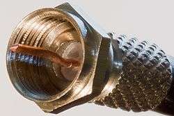
Male F Connector (threaded) | |||
| Type | RF coaxial connector | ||
|---|---|---|---|
| Production history | |||
| Designer | Eric E. Winston | ||
| Designed | Early 1950s | ||
| Manufacturer | Various | ||
| General specifications | |||
| Diameter |
Male Female | ||
| Cable | Coaxial | ||
| Passband | Typically DC to 750 MHz (2.2 GHz possible) | ||
The F connector is a coaxial RF connector commonly used for "over the air" terrestrial television, cable television and universally for satellite television and cable modems, usually with RG-6/U cable or, in older installations, with RG-59/U cable.
The F connector was invented by Eric E. Winston in the early 1950s while working for Jerrold Electronics on their development of cable television. [1]
In the 1970s it became commonplace on VHF television antenna connections in the United States, as coaxial cables replaced twin-lead, and later for UHF also.
The F connector is inexpensive, yet has good 75 Ω impedance match for frequencies well over 1 GHz [2] and has usable bandwidth up to several GHz. One reason for its low cost is that it commonly uses the solid conductor (center wire) of the specified types of coaxial cable as the pin of the male connector.
This design is subject to the surface properties of the inner conductor (which must be solid wire) and is not corrosion resistant; hence waterproof versions are needed for outside use (for example, on aerials).
Corrosion resistance can be improved by coating all bare copper wires with silicone grease. The male connector body is typically crimped, or sometimes screwed, on to the exposed outer braid. Female F Type connectors have an external 3/8-32 UNEF thread (9.5 mm diameter). Most male connectors have a matching internally threaded connecting ring, though push-on versions are also available.
Usage
The cable and satellite television entities (as a near standard practice) use compression fittings with F Type Connectors on customer premises.
F Type Coax connectors are probably the most suitable for domestic terrestrial, cable, and satellite TV installations where the delivery of very high frequency information is required. Belling-Lee connectors (IEC 169-2) [used on European terrestrial receivers] are not well suited for long haul building delivery of frequencies above 500 MHz, because the standard was designed around tube receivers and Mediumwave (or Shortwave) antennas (but workarounds exist) . Type F Connectors require slightly more care to properly install the Male connectors to the cable than the Belling-Lee type, with the exception of compression or flex type connections.
Weatherproof & Flex F connectors
Some component suppliers have in their catalog weatherproof (watertight) "F connectors". Tightness is achieved by inserting an O-ring of about 7 mm between the plug and the socket before tightening, making the union watertight.
Push-on (aka Flex) F Type connectors provide poorer shielding against microwave signals of high field strength. This leakage problem is more an artifact of bent or partly broken push on connectors, but is mostly not observed with compression connectors. Nearby television, FM radio, mobile & cordless phones, government radiolocation (54–1,002 MHz) [3] transmitters can potentially interfere with a CATV or DTH Satellite reception or operation if the Flex connector poorly installed.
 F connectors attached to a 4 way DiSEqC switch.
 A visual collection of standard and right angle F Type Coax connectors, a commonly used but less documented form of the F connector.
See also
References
- ↑ Electrical Connector. US Patent 3,537,065 by Eric Winston
- ↑ IEC 60169-24: "Radio-frequency connectors - Part 24: Sectional specification - Radio frequency coaxial connectors with screw coupling, typically for use in 75 Ω cable networks (type F)." (2009)
- ↑ Cityfreq United States Scanner Frequencies, Phone Numbers, and IP Addresses.
Further reading
- "F" Port (Female Indoor) Physical Dimensions, ANSI/SCTE 02 2006 (see www.scte.org).